
Joint CNC Machining: How Accuracy Is Actually Held
Joint CNC machining means cutting two or more mating features inside one setup, so the relationship between them comes from the machine rather than from refixturing. This page explains what drives that accuracy, which parts benefit, and when a single-setup approach is the wrong call.
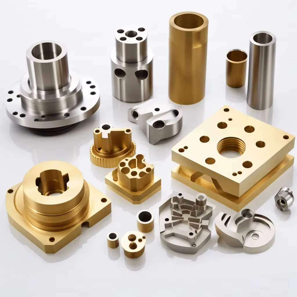
What Joint CNC Machining Really Means
A joint is any pair of surfaces that has to work together: a bore and its mating shaft, two bolt-hole patterns, a spigot and a shoulder, a hinge pin and its clevis. Their accuracy is a relationship, not a single dimension. Two features can each measure perfectly on their own and still fail to assemble if their relative position, angle or center distance drifts.
In joint CNC machining, those related features are cut without releasing the part from its workholding. The tool moves from one feature to the next under the same coordinate frame, so the machine's positioning accuracy and the part's location stay tied together. No re-clamping, no second datuming step, no operator deciding where the part sits this time.
That is the whole mechanism, and it is worth stating plainly. Every refixture resets the origin. Each reset adds its own error: fixture wear, chip entrapment between part and jaw, clamping distortion, the repeatability of the vise or chuck itself. Joint machining removes those resets from the stack. What remains is the machine's own volumetric error, tool deflection and thermal movement.
A useful way to think about it: separate setups multiply uncertainty, while a joint setup adds only the errors that live inside one continuous toolpath. When a print calls out a 0.02 mm center distance between two bores, the question is not which machine is accurate. The question is how many times the part gets located before both bores exist.
- 1Relationship, not sizeTolerance applies between features, so gaging one feature tells you nothing about the pair.
- 2Fewer datums, less stack-upEach refixture contributes its own locating error to the final relationship.
- 3Machine error remainsJoint machining does not remove thermal drift or tool deflection, only the reset errors.
- 4Print first, process secondRead the joint callouts before choosing workholding or machine type.
Where the Error Comes From
Positioning error on a good machining center is small. The bigger contributors to a failed joint are usually fixturing and heat. A vise jaw that grips a rough cast boss will seat the part differently on the second op than on the first. A three-jaw chuck with 0.03 mm runout will swing the whole bore pattern. These are not machine faults, and no amount of ballbar calibration will fix them.
Thermal drift is the slow one. A spindle running at 12,000 rpm for two hours grows in Z. A 500 mm aluminum part warmed by cutting can expand several hundredths of a millimeter before the last feature is cut. If the first bore was cut cold and the last bore cut warm, the center distance between them carries that difference directly.
Tool deflection scales with reach. A Ø6 mm end mill hanging 60 mm out of the holder will push away from the wall under load, and the error grows as the tool wears. Rough the joint features first, then finish them with a fresh cutter at short gage length. Take a spring pass on tight bores. These are cheap habits that show up on the CMM.
Material behavior matters too. Thin-wall aluminum joint housings move when clamps release, so the measured part differs from the machined part. Titanium and Inconel cut hotter and spring back more. For those, plan the sequence so the critical joint is finished last, after the part has settled and the spindle has reached steady temperature.
- 1Fixture repeatabilityChip entrapment and jaw wear show up as joint error, not as a size error.
- 2Thermal growthWarm spindles and warm parts shift long center distances.
- 3Tool deflectionLong gage length and worn edges bend the cut away from nominal.
- 4Release distortionThin walls move when the clamps come off, so sequence the joint last.
Which Machine Type Fits Which Joint
A 3-axis mill can hold a joint when all the related features face one direction. Two bores on the same face, a bolt circle on a flange, a pocket and the shoulder beside it. One setup, one datum, done. The limit is reach. If the tool cannot get to a feature without the part being turned, the joint breaks.
A 4-axis machine adds a rotary table, usually Ø400 mm on our mills. Now two opposed faces can be cut in one setup, and a bore can be interpolated while the table indexes. This covers most shaft-like and bracket-like joints where the related features sit around one axis. It is often the most cost-effective answer for a joint that would otherwise need two operations.
Simultaneous 5-axis does something different. The tool tip stays normal to a curved surface while the table and spindle move together, which lets a compound-angle port, an angled pad and its mating bolt holes all come from one setup. On a part with a 30-degree face and a bore crossing it, 5-axis removes the re-datum entirely. That is where the accuracy gain is real.
The trade is not free. Five-axis toolpaths run longer and need more prove-out, and not every joint needs them. If the related features all face one way, a 3-axis setup will be faster and easier to inspect. Match the machine to the geometry, not to the spec sheet.
- 13-axisRelated features on one face; fastest and simplest to verify.
- 24-axisFeatures around one axis; opposed faces without a second op.
- 35-axisCompound angles and curved surfaces; removes re-datum entirely.
- 4Mill-turnTurns and cross-features on one shaft in a single setup.
What to Change on the Print
Tolerance the joint, not every surface. A print that calls ±0.005 mm on all faces forces an expensive process for features nobody measures against each other. Put the tight tolerance on the two bores that must align, and let the clearance surfaces sit at ±0.05 mm. This alone can cut cycle time without touching function.
Give the machinist a datum that exists on the blank. A joint callout referenced to a surface that only appears after the first op forces a setup the print did not intend. If the design allows, reference the joint features to a face or a pair of holes that are present from the first cut, and the whole joint can come from one location.
Watch corner radii and tool access. A joint bore with a sharp internal corner forces a small cutter with long reach, which means deflection and slower feed. A 0.5 mm corner radius allows a larger, stiffer tool. On deep joints, add a relief groove where the print permits so the tool does not rub at full depth.
Say what the joint does. A locating bore needs a press fit and a fine finish. A clearance bore for a bolt needs position, not size. Engineers who write the function on the drawing get a better quote, because the shop can pick the process from the requirement instead of guessing from the tolerance block.
- 1Tolerance the pairTighten only the features that mate; loosen the rest.
- 2Datum that existsReference a face or holes present from the first cut.
- 3Corner radiiA 0.5 mm radius lets a stiffer, shorter tool do the job.
- 4State the functionLocating, clearance or sealing changes the process choice.
How to Prove the Joint Is Good
Measure the relationship, not just the features. A CMM report that lists bore diameters tells you size. You need center distance, angular position and perpendicularity between the mating features, measured from a datum that matches the drawing. Ask for the report before shipment, not after the parts reach the line.
For bores that must align, a plug gage or a mating pin test is faster than a full CMM routine and closer to how the part will be used. Push the pin through both bores while the part sits in its fixture. If it binds, the CMM will usually show why, but the pin test catches problems the print never described.
Watch the finish on sealing joints. A bore that holds an O-ring needs Ra 0.8–1.6 μm and no axial scratches. A roughing pass left at Ra 3.2 μm will leak regardless of how good the position is. Fine boring or a reaming pass on the last 0.1 mm is often the difference between a passing and a failing joint.
Finally, check the first article cold and warm. Measure parts from the start of a run and from hour three. If the center distance moves, you have found thermal drift before it becomes a rejected lot. This is a five-minute check that saves a week.
- 1CMM relationship reportCenter distance, angle and perpendicularity from the drawing datum.
- 2Pin testA mating pin through both bores confirms function in seconds.
- 3Sealing surfacesHold Ra 0.8–1.6 μm with no axial scratches.
- 4Cold vs. warm checkCompare first-article and mid-run parts for drift.
Joint Geometry vs. Setup Strategy
Pick the row that matches the part.
| Joint geometry | Best setup | Typical tolerance | Watch out for |
|---|---|---|---|
| Bores and holes on one face | 3-axis, single datum | ±0.005 mm | Chip entrapment under clamps |
| Features on two opposed faces | 4-axis with rotary table | ±0.01 mm | Rotary table runout and backlash |
| Compound angle plus cross bore | Simultaneous 5-axis | ±0.005 mm | Longer prove-out and cycle time |
| Shaft with cross-drilled holes | Mill-turn center | ±0.01 mm | Bar pull-out between operations |
| Thin-wall housing, tight joint | 5-axis, joint finished last | ±0.01 mm | Release distortion after unclamping |
| Large frame, joint over 1,000 mm | 3-axis, single datum | ±0.02 mm | Thermal drift over long cycles |
The Verdict
If the related features face one direction, a 3-axis setup with one datum is enough. If they wrap around an axis, use 4-axis. Only reach for simultaneous 5-axis when the joint crosses a compound angle or a curved surface, because that is the case where removing the re-datum actually buys accuracy rather than cycle time.
Common Questions
Can joint CNC machining hold ±0.005 mm between two bores?
Yes, when both bores are cut in the same setup on a machine with that volumetric accuracy and the part stays thermally stable through the cycle. The tolerance applies to the center distance, not to each bore's diameter, and it is measured from the drawing datum.
If the bores sit on opposite faces and have to be cut in two operations, the practical limit moves closer to ±0.01 mm because each refixture adds its own locating error.
When is one setup worse than two?
When the joint features are so far apart that reaching them in one setup forces a long, weak tool or an awkward part orientation that invites chatter. On large frames, letting the part sit flat on a big table often gives a better cut than tilting it for access.
Cost is the other case. If the joint tolerance is ±0.05 mm and the two operations are simple, adding five-axis time does not buy anything the customer will measure.
Does the material change the joint strategy?
It changes the sequence more than the machine. Aluminum joint housings move less from heat but more from clamping release on thin walls. Titanium and Inconel cut hotter, so the joint should be finished after the spindle reaches steady temperature.
Plastics such as POM and PEEK spring back after the cutter passes. Leave 0.2–0.3 mm for a finishing pass and keep the tool sharp, or the joint will close up after unclamping.
How do I specify a joint on the drawing?
Reference the mating features to a common datum, give the center distance and the angular tolerance between them, and add a note about which surfaces seal or locate. That note lets the shop choose boring, reaming or interpolation from the function instead of guessing.
Also state the finish on sealing bores. Ra 0.8–1.6 μm is typical for an O-ring joint. A position callout alone will not stop a leak.
What inspection data should I ask for?
A first-article report with center distances, angular positions and perpendicularity between the joint features, measured from the drawing datum. Size data on each feature is not enough for a joint.
For high-volume runs, ask how in-process monitoring is done between the first article and final inspection. On our runs, 100% inspection happens before shipment, and reports are available on request.
Can you machine a one-off joint prototype?
Yes. There is no minimum order quantity, so a single prototype and a 10,000-part run go through the same process planning. Quotation and DFM analysis come back within 12 hours, and production can start within 24 hours of approval.
Uploads stay confidential, and an NDA is available on request if the joint geometry is sensitive.
Send Us the Joint Drawing
A 12-hour quote with a DFM note on your joint callouts, one part or ten thousand.
12-hour quote±0.005 mm tolerance100% inspection
More Machining Notes
We publish setup notes, tooling trials and inspection data from the factory floor.











