
Introduction to CNC machining center operation: mastering basic operating techniques
This page explains what actually happens inside a CNC machining center during a run, from work offset to tool offset to chip evacuation. It is written for engineers and buyers who need to judge whether a process plan is sound, not for hobby machinists. By the end you should be able to read a setup sheet and see where a job will go wrong.
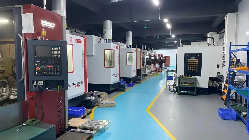
What CNC machining center operation does during a cut
A CNC machining center is a positioning system with a spindle attached. The controller never sees your part. It sees coordinates, and it trusts the numbers you gave it. Every CNC machining center operation starts from a work offset: a stored distance between machine zero and the corner or center you picked as datum. If that offset is wrong by 0.1 mm, every feature on the part is wrong by 0.1 mm in the same direction, no matter how good the cutter is.
From the work offset, the controller adds tool length and tool radius compensation. Length offset sets how far the tool tip sits below the gauge line. Radius offset shifts the path by half the cutter diameter so the finished wall lands on the drawing line. Both are numbers an operator enters by hand or reads from a presetter. Both drift. A cutter pulled 0.02 mm short in the holder will cut a pocket floor 0.02 mm high, and no amount of re-measuring the part will fix that.
This is why the first article matters more than the hundredth. On the first part you confirm the offset chain: datum position, tool length, tool radius. After that you are only watching for drift from thermal growth, chip packing, and tool wear. A spindle that runs for two hours at 12,000 rpm grows in Z. On a ±0.005 mm job that growth is visible.
Machine size sets the ceiling on what you can hold. A 4,000 mm travel handles long extrusions and frame rails. A 500 × 500 × 450 mm envelope handles most brackets and housings. The controller logic is the same at both ends. The difference is how much of the error budget gets eaten by the machine itself.
- 1Work offsetDistance from machine zero to your datum. Wrong once, wrong everywhere.
- 2Length offsetTool tip position. Sets depth on every Z move.
- 3Radius offsetHalf the cutter diameter, applied to the path, not the drawing.
- 4First articleConfirms the whole offset chain before the run is released.
How workholding decides the achievable tolerance
A vise holds a part by squeezing it. That squeeze is a force, and the part answers with elastic deflection. Clamp a thin-walled aluminum housing hard enough to keep it from moving during a roughing pass, and the walls bow inward. The cutter removes material from a bowed wall. Release the vise and the wall springs back, and now it is thin in the middle and thick at the ends.
The fix is to control where the force goes. Support the part under the cutting zone rather than at its extremities. Use soft jaws bored to the part profile so contact is distributed. For thin sections, back the wall with a low-melt alloy or a machined support plug. On a 2 mm wall in 6061, the difference between point clamping and full-profile support can be 0.05 mm of flatness, which is ten times the tolerance on a tight job.
Fixtures also set your setup count. Every time a part moves to a new face, you re-establish a datum and add stack-up error. A four-sided part held in a tombstone fixture on a four-axis mill machines three faces in one setup. The same part on a three-axis machine needs two or three setups, and each one adds a re-clamp error you cannot measure away.
For parts that cannot be held rigidly at all, consider whether the geometry should be machined in a softer state. Machining a hardened 440C or 17-4PH part after heat treat is slow and hard on tools. Roughing before heat treat and finishing after adds a setup, but it keeps the cutting forces low where it counts.
- 1Clamping forceEvery vise closes like a spring. Plan where the part will move.
- 2Soft jawsBored to the profile, they spread contact instead of concentrating it.
- 3Setup countEach new face adds a datum and a re-clamp error.
- 4Hardened partsRough soft, finish hard. Two setups, less tool wear.
Feeds, speeds, and the surface finish you actually get
Surface finish comes from the tool path, not from the spindle speed alone. A ball nose cutter stepping over 0.2 mm leaves scallops you can feel with a fingernail. Ra 0.8–1.6 μm is realistic on a stepped path with a sharp cutter. Ra 0.2–0.8 μm needs a smaller stepover, a fresh edge, and a machine that does not chatter.
Chip load per tooth is the number that matters for tool life. Too low and the edge rubs, work-hardens the surface, and dulls fast. Too high and the tool deflects, the wall goes tapered, and the finish tears. On aluminum 6061 a 10 mm three-flute carbide end mill at 8,000 rpm commonly runs 0.05–0.10 mm per tooth. On 316 stainless, drop the surface speed and keep the chip load up so the cut stays under the work-hardened layer instead of skating on it.
Coolant choice follows the material. Aluminum floods well and clears chips fast. Titanium and Inconel generate heat at the edge, so high-pressure through-spindle coolant reaches the cut zone where flood cannot. Plastics like POM and PEEK cut clean with air blast; liquid coolant can swell them or leave a residue that ruins a bonded assembly.
Climb milling is the default on a rigid machine. It pulls the cutter into the material and leaves a better wall. On a light machine with a long tool, conventional milling sometimes gives a more stable cut, at the cost of finish and tool life. That trade is real and worth naming in the setup sheet.
- 1Chip loadPer-tooth thickness. The real driver of tool life and finish.
- 2StepoverSets scallop height on curved surfaces. Smaller means slower.
- 3CoolantFlood for aluminum, through-spindle for titanium, air for plastics.
- 4Climb millingBetter wall on a rigid machine. Not always better on a light one.
Choosing the machine class for the feature
Match the geometry to the axis count and the tolerance follows.
| Feature type | Best machine class | Why |
|---|---|---|
| Prismatic plate, 3 faces | 4-axis mill with tombstone | One setup, three faces, no re-clamp |
| Complex contoured surface | 5-axis simultaneous | Tool stays normal to the surface |
| Long extrusion, 2,000 mm | 3-axis with 4,000 mm travel | Bed length, not axis count, is the limit |
| Turned shaft with milled flats | Mill-turn center | Turning and milling in one setup |
| Thin-wall housing, 2 mm | 3-axis, soft jaws, light passes | Rigidity matters more than axes |
| Hardened 17-4PH detail | 3-axis, finish after heat treat | Low force on the finishing pass |
| Small batch, 20 parts | 3-axis, quick-change fixture | Setup time dominates the cost |
When the axis count matters, and when it does not
If the part has features on four or more faces, choose a 4-axis or 5-axis machine and pay for it in one setup. If the part is flat and has one critical face, a well-fixtured 3-axis machine will hold the same tolerance for less money, and the axis count is not your constraint.
Questions engineers ask before releasing a job
How tight can a CNC machining center operation hold on a normal run?
On a well-fixtured part in 6061 or 303 stainless, ±0.005 mm is achievable on critical features, and we inspect 100% before shipment.
The number that matters is not the best single part. It is the spread across the run. Thermal drift, tool wear, and re-clamping set that spread, not the machine spec sheet.
Does a 5-axis machine always give a better finish?
No. A 5-axis machine keeps the tool normal to a contoured surface, which removes the need for multiple setups and improves access.
On a flat plate, a rigid 3-axis machine with a solid fixture will match or beat it, because there is less rotating mass and fewer error sources in the loop.
What makes a thin-wall part go out of tolerance?
Clamping force, mostly. The vise bows the wall inward, the cutter removes material from the bowed shape, and the wall springs back after release.
Support the wall under the cut, use bored soft jaws, take lighter radial passes, and check flatness with the part still clamped to see the difference.
Why does the first article cost more than the parts that follow?
The first article confirms the whole offset chain: datum, tool length, tool radius, and fixture position. That takes setup time and inspection time.
Once the chain is proven, the run is mostly monitoring for drift. We can start production within 24 hours of a released plan, and parts typically ship in 3–5 days.
When should a job be roughed before heat treat?
When the material hardens past the point where a finishing cutter can remove stock efficiently. 17-4PH, 440C, and tool steels are the common cases.
Rough soft, leave 0.3–0.5 mm of stock, heat treat, then finish. It adds a setup but keeps cutting forces low on the final pass, which protects the tolerance.
How do we know the setup sheet is realistic?
It should name the datum, the fixture, the tool numbers, the offsets, the coolant, and the inspection points. If it does not say where the part is held, it is not a plan yet.
Send us the drawing and we will return a DFM analysis with the quotation, normally within 12 hours.
Send the drawing, get a process plan
Upload your files and we will tell you which machine class fits the geometry, where the tolerance risk sits, and what the setup will look like.
12-hour quote100% inspectionNo minimum order
More from GreatLight
We publish setup notes, tooling trials and inspection data from the factory floor.











