
Introduction to the Vertical CNC Machining Center
A vertical CNC machining center keeps the spindle vertical and moves the tool down onto a clamped workpiece. This page explains the axis layout, the spindle and table geometry, what part shapes fit, and the cases where a horizontal or 5-axis machine is the better call.
In this article
- 1
- 2
- 3
- 4
- 5
- 6
- 7
Key takeaways
What a vertical CNC machining center actually does
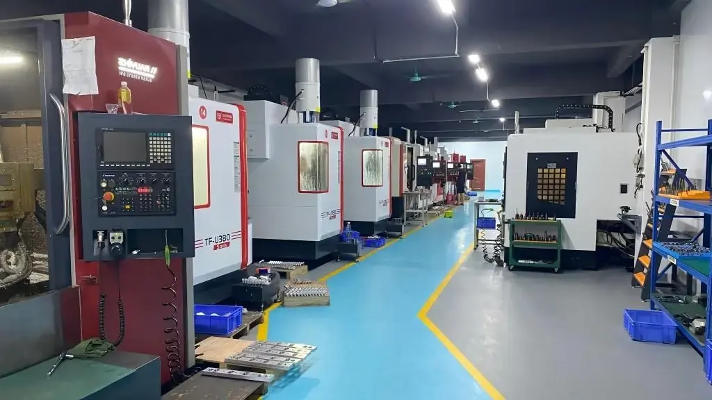
A vertical CNC machining center is a computer numerical control mill with the spindle mounted vertically above the table. The tool spins on a vertical axis and travels in X and Y along the table plane, then feeds down in Z to reach the cut. The workpiece sits on a flat table or fixture, so the operator can see the cutting zone from the front of the machine.
That layout shapes everything downstream. The part is usually loaded on its largest flat face, which makes workholding simple and repeatable. Clamping a block in a vise, setting a zero point, and cutting a pocket are quick jobs on this machine.
The spindle takes tools from a carousel or a chain magazine, so a single program can drill, tap, rough and finish without a manual tool change. Tool tapers are common in 30, 40 and 50 sizes. A larger taper carries more torque and a stiffer cut, which matters when you push a face mill through 4140 steel.
Most vertical centers are three-axis machines. Add a rotary table and you get a fourth axis for indexing or continuous rotation. Add two rotary axes and the machine becomes a five-axis unit, which tilts the tool or the part to reach features on several faces in one setup.
- 1Spindle orientationVertical, pointing down at the table.
- 2Typical axesX, Y, Z as standard; A or B rotary as an option.
- 3WorkholdingVise, chuck, fixture plate or vacuum table on a flat surface.
- 4Tool changeAutomatic, from a carousel or chain magazine.
Axis travel, table size and what fits on the machine
Travel limits decide whether a part fits before you ever think about tolerance. A compact vertical CNC machining center may offer 500 × 310 × 200 mm of X, Y and Z travel. A mid-size machine runs around 600 × 600 × 600 mm or 750 × 1,150 × 550 mm. Large bridge-style centers reach 4,000 × 400 × 150 mm for long, shallow parts such as rails and beams.
Table size is not the same as travel. A 1,000 mm table usually cannot cut across the full 1,000 mm because the tool needs room to reach the edges and the fixture eats into the envelope. Keep 50 to 100 mm of clearance on each side when you check a part against a machine.
Spindle nose to table distance sets the maximum part height. If a tall part plus its fixture is taller than that gap, the job moves to a machine with more Z clearance or a different orientation. This is the single most common reason a quote comes back with a different machine than the customer expected.
Part weight matters too. A rotary table rated at 200 kg will not hold a 400 kg weldment, and an oversized part on a small table can flex under cutting load. Weight, size and travel should all be checked against the same machine model.
- 1Compact class500 × 500 × 450 mm or 500 × 310 × 200 mm travel.
- 2Mid class600 × 600 × 600 mm and 750 × 1,150 × 550 mm travel.
- 3Large classUp to 4,000 × 400 × 150 mm for long parts.
- 4Rotary tableØ400 mm is a common fourth-axis size.
Why chip evacuation and rigidity favor the vertical layout
Gravity is a real process advantage on a vertical machine. Chips fall away from the cut and drop to the bottom of the enclosure, so the flute stays clear and the tool is less likely to recut a chip. Recutting is a fast route to broken tools and poor surface finish.
That said, deep pockets still trap chips. A tool cutting a cavity deeper than two times its diameter pushes chips upward around the shank, and coolant has to carry them out. High-pressure through-spindle coolant, or a short peck cycle, is often the fix. Without either, the tool rubs and the finish turns rough.
Rigidity depends on the tool, not just the machine. A stub-length end mill in a shrink-fit holder cuts far more accurately than a long tool in a collet. Long tools deflect under load, and that deflection shows up as taper in a wall or a bore that comes out undersize.
Thermal growth also moves the numbers. A spindle running at 12,000 rpm for an hour gets longer, and the Z zero shifts with it. Warm-up programs and in-process probing keep the tolerance band stable across a long run. This is why a machine that holds ±0.005 mm on the first part can drift on the two-hundredth.
- 1Chip pathDown and away, so flutes clear faster.
- 2Deep pocketsUse through-spindle coolant or peck cycles.
- 3Tool reachKeep length-to-diameter under about 4:1 where possible.
- 4Thermal driftWarm up the spindle and probe between batches.
Materials and surface finish on a vertical center
Aluminum is the easy case. Grades such as 6061-T6, 7075 and 2024 cut at high spindle speeds and leave a clean finish with the right cutter geometry. A three-flute carbide end mill with polished flutes and good coolant flow handles most pockets and profiles without drama.
Stainless steel behaves differently. Grades 304 and 316 work-harden if the tool rubs instead of cutting, so the feed per tooth has to stay high enough to bite under the hardened layer. 17-4PH in the H900 condition needs sharper tools and more rigid setups again. Light passes at low feed are the wrong answer here.
Titanium and nickel alloys such as Ti-6Al-4V and Inconel punish heat. The cutting zone runs hot, tool life drops fast, and coolant delivery matters more than spindle speed. Higher torque at lower rpm is the normal approach, and the cycle time is simply longer than an aluminum job of the same shape.
Plastics and composites have their own rules. PEEK and carbon fiber need sharp, uncoated tools and dust extraction, because the chips are abrasive and the dust is a health and finish problem. Surface finish targets on our machines run from Ra 1.6–3.2 μm as machined down to Ra 0.2–0.8 μm after finishing operations.
- 1AluminumHigh speed, three-flute carbide, generous coolant.
- 2StainlessKeep feed per tooth high to stay under the work-hardened skin.
- 3Titanium and InconelLower rpm, higher torque, flood or high-pressure coolant.
- 4Plastics and compositesSharp uncoated tools plus dust extraction.
Where the vertical layout runs out of room
Five faces of a cube cannot be cut from one setup on a three-axis vertical machine. Each new face means a new fixturing operation, a new zero point, and a fresh chance to stack up error. On a part with a ±0.05 mm true position callout across two faces, that stacking is often the deciding cost.
Deep bores and long cavities expose the reach limit. When the depth is more than four times the tool diameter, the tool has to be long and thin, and the cut gets unstable. A horizontal machine with the spindle on its side can often reach the same pocket with a shorter, stiffer tool.
Heavy material removal is another boundary. A vertical machine with a 40 taper can rough efficiently, but a big block of 4340 steel with 60 percent of its volume to remove may run faster on a horizontal with a larger taper and a pallet changer. Cycle time, not accuracy, drives that choice.
Long, narrow parts such as shafts and rails are usually better on a mill-turn center or a lathe with live tooling. A vertical machining center can do the milling side, but turning a Ø300 mm shaft on a flat table is awkward and slow.
- 1Multi-face featuresEach new face adds a setup and a tolerance stack.
- 2Deep cavitiesDepth over 4× diameter needs a shorter, stiffer tool path.
- 3Heavy roughingHorizontal machines with pallets move more metal per hour.
- 4Round partsMill-turn or live-tool lathes handle turning better.
Vertical, horizontal or five-axis: picking the right machine
Match the part to the machine before you compare price.
| Part condition | Vertical 3-axis | Horizontal | 5-axis |
|---|---|---|---|
| Flat plate with pockets and holes | Best fit | Works, slower setup | Overkill |
| Cube with features on 4+ faces | Multiple setups | Good with rotary | Best in one setup |
| Deep cavity, depth > 4× Ø | Tool deflection risk | Shorter reach | Tilted tool access |
| Large weldment, heavy roughing | Size limits apply | Best metal removal | Rarely used |
| Shaft or round part | Awkward | Limited | Mill-turn instead |
| Tight true position across faces | Tolerance stacking | Better | Best accuracy |
| Prototype, one to ten parts | Fastest to program | Setup heavy | Fastest to complete |
The short answer
Choose a vertical CNC machining center for prismatic parts with features on one or two faces, tight pockets, and short lead times. Move to a horizontal when the part needs heavy roughing or many faces, and to a 5-axis center when true position across several faces decides whether the part passes inspection.
Questions engineers ask next
How tight a tolerance can a vertical CNC machining center hold?
With a rigid setup, sharp tooling and temperature control, our machines hold ±0.005 mm (±0.0002 in) on critical features. That number is a process result, not a machine spec.
The fixture, the tool holder, the material condition and the inspection method all sit inside that band. On a thin-wall aluminum part, wall deflection may dominate and the practical limit is looser. We confirm the achievable tolerance per feature during DFM review.
What is the largest part you can machine?
Our maximum processing size is 4,000 mm, with a large machine travel of 4,000 × 400 × 150 mm. Mid-size machines cover 750 × 1,150 × 550 mm and 600 × 600 × 600 mm, and compact machines cover 500 × 500 × 450 mm and 500 × 310 × 200 mm.
Send the part envelope, not just the drawing dimensions. Fixture space and tool clearance usually reduce the usable area below the nominal travel.
Do I need a fourth axis?
A fourth axis pays off when the part has features on two or more sides and you want them cut without re-clamping. A Ø400 mm rotary table is a common size for that work.
If all the features sit on one face, a fourth axis adds cost and setup time with no accuracy gain. We check the drawing before recommending it.
Which materials do you run on these machines?
Aluminum grades 6061, 6061-T6, 2024, 5052, 5083, 6063, 6082, 7075 and ADC12; stainless 303, 304, 316, 316L, 420, 430, 431, 440C and 17-4PH; steels 1018, 1045, 4130, 4140, 4340, A36 and tool steel.
We also cut copper and brass, titanium grades TA1, TA2 and TC4 (Ti-6Al-4V), Inconel, magnesium AZ31B and AZ91D, plus plastics including ABS, PC, PMMA, POM, PA, PEEK, PP, HDPE and carbon fiber.
What lead time should I plan for?
Quotation and a free DFM analysis come back within 12 hours. Production can start within 24 hours of approval, and parts ship in 3–5 days.
Those figures assume the drawing is manufacturing-ready and the material is in stock. A part that needs a new fixture or a hard-to-source alloy will take longer, and we say so at the quote stage rather than after the order.
Can you inspect the parts before they ship?
Yes. Every part gets raw material check, in-process monitoring and final inspection before shipment, and we inspect 100 percent of the order.
Inspection reports are available on request. If your drawing calls out a CMM report, a first-article report or a specific sampling plan, note it on the RFQ so the inspection step is quoted with the machining.
Send your drawing and get a machinability read
Upload a STEP file and we return a quote plus DFM notes within 12 hours. Your files stay confidential, and an NDA is available on request.
12-hour quote100% inspectionNo minimum order quantity
More machining notes
We publish setup notes, tooling trials and inspection data from the factory floor.











