
In the world of precision parts machining and customization, the allure of a DIY CNC machine is undeniable. It represents the ultimate fusion of personal ingenuity and manufacturing capability, allowing hobbyists, engineers, and small startups to bring complex designs to life. However, the bridge between a functioning machine and one capable of producing truly precision parts is calibration. A poorly calibrated DIY CNC machine will produce parts with dimensional inaccuracies, poor surface finishes, and unreliable repeatability—issues that are unacceptable in professional contexts. This guide delves into the systematic process of calibrating your DIY CNC machine, transforming it from a promising tool into a reliable asset for prototyping and low-volume production.
H2: Understanding the “Why”: The Critical Role of Calibration in CNC Machining
Before touching a wrench or software setting, it’s crucial to understand what calibration achieves. At its core, calibration ensures that the machine’s movements in the physical world perfectly match the commands sent from the Computer-Aided Manufacturing (CAM) software. Any discrepancy—whether from mechanical backlash, misaligned axes, or incorrect motor steps—is magnified in the final workpiece. For professionals seeking to create functional prototypes or custom components, this process is non-negotiable. It’s the foundational step that separates a tool that moves from a tool that manufactures with precision.
H3: Pre-Calibration Checklist: Laying the Groundwork
A successful calibration begins with preparation. Attempting to calibrate a machine with underlying mechanical issues is futile.
Mechanical Integrity: Ensure all frame members are square and rigid. Check for loose bolts, particularly on gantry assemblies, linear rails, and spindle mounts. Any flex or play will sabotage your calibration efforts.
Squareness of Axes: This is paramount. Use a precision machinist’s square to check that the X-axis is perpendicular to the Y-axis, and that the Z-axis is perpendicular to the X-Y plane. Many DIY machine inaccuracies stem from a lack of squareness.
Belt Tension or Lead Screw/Ball Screw Alignment: For belt-driven machines, belts should be taut without being overtightened. For screw-driven machines, ensure the coupling between the motor and screw is secure and that the screw is properly aligned with its nut to avoid binding.
Flat and Level Work Surface: Your machine table or spoilboard must be flat. Use a dial indicator on the spindle to map the table’s surface. Significant deviations may require re-surfacing the spoilboard.
H2: The Step-by-Step Calibration Procedure
Follow this sequence for comprehensive calibration. Document all your original and new settings.
H3: Step 1: Electronics & Firmware Configuration
This step defines the relationship between electrical pulses and physical movement.
Determine Steps per Millimeter (or Inch): This is the most critical firmware setting. You need to calculate how many stepper motor steps result in one unit of movement.
Formula: Steps per Unit = (Motor Steps per Revolution * Microstepping Setting) / (Drive Mechanism Pitch)
Example (Lead Screw): A motor with 200 steps/rev, using 16x microstepping, driving a 5mm pitch lead screw: (200 * 16) / 5 = 640 steps/mm.
Example (Belt Drive): Same motor, driving a 20-tooth pulley with a 2mm pitch GT2 belt: Pulley Circumference = 20 teeth * 2mm = 40mm. So, (200 * 16) / 40 = 80 steps/mm.
Input into Controller: Enter these calculated values into your machine’s control software (e.g., GRBL, Mach3, LinuxCNC, or the machine’s dedicated controller).
H3: Step 2: Backlash Measurement and Compensation
Backlash is the “slop” or lost motion that occurs when reversing direction. It causes rounded corners and dimensional errors.
Measurement: Secure a dial indicator to the machine bed. Touch the indicator’s probe to a solid part of the moving gantry or spindle. Command the machine to move a small distance (e.g., 1mm) in one direction, note the indicator, then command it back to the start. The difference between the final indicator reading and zero is your backlash.
Compensation: Perform this measurement for all three axes (X, Y, Z). Most control software has a backlash compensation setting. Input the measured value (e.g., 0.05mm). Note: While software compensation can help, the ultimate goal is to mechanically minimize backlash through proper pre-loading of anti-backlash nuts or high-quality components.
H3: Step 3: Verifying Movement Accuracy
Now, test if the calculated steps-per-unit are correct.
The Cut-and-Measure Test: Use a precise measuring tool (digital calipers, micrometer). Command the machine to move a large, exact distance (e.g., 200mm). Physically measure the actual distance traveled using a gauge block or the calipers against a fixed reference.
Calculating Error & Tuning: If you commanded 200mm but measured 199.8mm, you have a -0.1% error. Adjust your steps-per-unit setting proportionally: New Steps = Old Steps * (Commanded Distance / Measured Distance). In this case: New Steps = Old Steps * (200 / 199.8). Repeat until movement accuracy is within your tolerance (e.g., ±0.01mm over 200mm).
H3: Step 4: Spindle Runout Check
A spindle with excessive runout will cause tool deflection, poor finish, and accelerated tool wear.
Test Method: Place a dial indicator’s probe against a precision ground rod (a test bar) held in the collet. Rotate the spindle by hand.
Interpretation: The total indicator reading (TIR) is your runout. For precision work, aim for less than 0.01mm TIR at the tool tip. High runout may indicate a damaged collet, spindle bearing wear, or a dirty taper.
H2: Advanced Calibration & Software-Assisted Mapping
For those seeking the highest level of accuracy, especially on larger-format DIY machines, these advanced steps are essential.
Auto-Squaring (Dual-Drive Y-Axis): If your machine uses two motors on the Y-axis, use software features (like in GRBL) to auto-square the gantry each time it homes. This compensates for minor misalignment that can occur during operation.
Bed Leveling / Surface Mapping: While common in 3D printing, this is equally valuable for CNC, especially for machining large, flat surfaces. A probe can map the height variations of your bed. The CAM software can then use this map to adjust the Z-height during machining, ensuring uniform cutting depth across the entire workpiece.
H2: Validation: The Proof is in the Part
After calibration, you must validate the machine’s performance by making a test part.
Design a Geometric Test Piece: Include features that test all aspects: circles (testing axis interpolation and backlash), squares (testing perpendicularity), pockets of precise depths (testing Z-axis accuracy), and a grid of holes (testing positioning repeatability).
Machine and Measure: Machine the test part from a stable material like acrylic or machinable wax. Use precision measuring tools to check all critical dimensions.
Analyze and Iterate: Any consistent errors point to a specific calibration issue. Revisit the relevant calibration step.
Conclusion: The Limits of DIY and the Power of Partnership
Meticulously calibrating your DIY CNC machine can yield impressive results, suitable for prototypes, hobby projects, and learning. It cultivates a deep understanding of the mechanics behind precision parts machining and customization. However, it’s vital to recognize the inherent limitations of scale, material capability, and ultimate precision ceiling of most DIY systems.
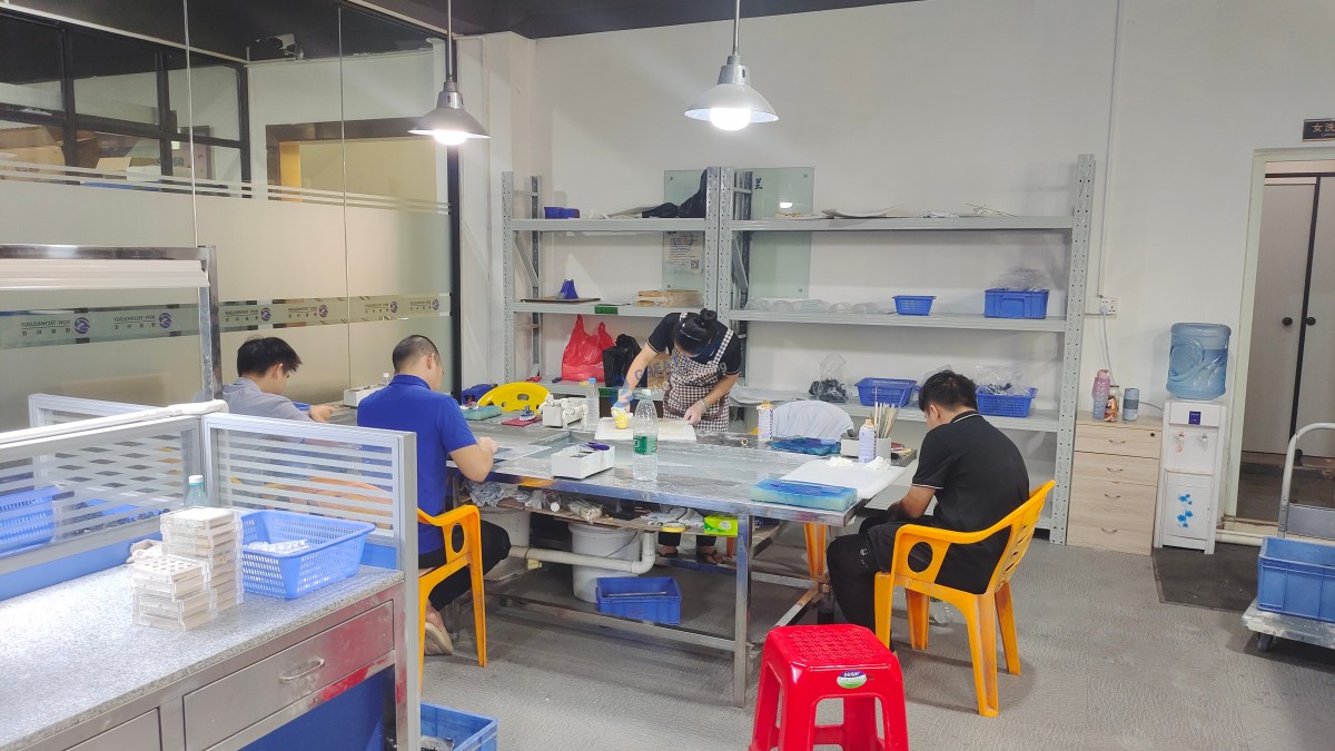
When your project demands guaranteed tolerances within ±0.025mm or even ±0.001mm, involves challenging materials like titanium or Inconel, or requires the production of mission-critical components, the expertise and industrial-grade equipment of a professional partner become indispensable. This is where a manufacturer like GreatLight CNC Machining Factory demonstrates its value. Their arsenal of advanced multi-axis CNC centers, governed by rigorous ISO-certified quality systems (like ISO 9001:2015 and IATF 16949), exists to solve the very precision challenges that push DIY machines to their limits. They provide the reliability, scalability, and material expertise that allow innovators to move confidently from a calibrated prototype to a flawlessly executed production run. Think of your well-tuned DIY machine as the perfect sketchpad for innovation, and a partner like GreatLight Metal as the industrial press that brings your most ambitious designs to life at scale.
Frequently Asked Questions (FAQ)
Q1: How often should I recalibrate my DIY CNC machine?
A: It depends on usage. For frequent use, a quick backlash and squareness check every 40-50 hours of runtime is wise. A full recalibration should be performed after any mechanical change (e.g., replacing a bearing, lead screw, or motor), or if you notice a consistent decline in part accuracy.
Q2: My machine has acceptable backlash (e.g., 0.03mm), but I’m still getting rounded corners. Why?
A: Rounded corners can also be caused by low acceleration/deceleration settings or a lack of rigidity. The machine may be physically slowing down too much before a direction change. Try increasing acceleration settings incrementally, and re-check all mechanical fasteners for tightness.
Q3: Can software compensation fix all mechanical problems?
A: No. Software compensation is a corrective overlay, not a cure. It can mask small amounts of backlash or scaling error, but it cannot fix problems like a bent lead screw, a severely out-of-square frame, or a wobbly spindle. Always address the root mechanical cause first.
Q4: What are the most common mistakes during DIY CNC calibration?
A: The top three are: 1) Skipping mechanical checks and trying to fix everything in software, 2) Using inaccurate measuring tools (e.g., a cheap plastic caliper) to set steps-per-unit, and 3) Not allowing the machine to warm up before taking calibration measurements, as thermal expansion can alter dimensions.
Q5: When should I consider outsourcing to a professional 5-axis CNC machining service instead of using my DIY machine?
A: Consider professional services when: you require tolerances tighter than ±0.05mm; you need to machine hard metals or advanced engineering plastics; your part geometry is highly complex with undercuts or compound angles; you need surface finishes better than Ra 1.6µm; or when project risk, timeline, and consistency are paramount. For insights into how leading manufacturers operate, you can explore industry networks like those on LinkedIn.



















