
Guitar pedal enclosure die casting
This page explains how a die-cast pedal shell is actually made, why alloy and wall thickness decide how it sounds and holds up, and where CNC finishing has to take over. Written for pedal builders, OEMs, and hardware engineers who need to judge a quote rather than read a brochure.
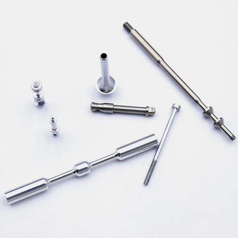
How guitar pedal enclosure die casting works
High-pressure die casting pushes molten metal into a hardened steel die at high speed. For a pedal shell, that means the walls, the internal battery pocket, the corner radii, and any mounting bosses form in a single shot. A typical shot cycle runs 30 to 90 seconds depending on wall thickness and part size. The die itself is the expensive part, so this process pays off when you need the same shape hundreds or thousands of times.
The metal enters through a gate, fills the cavity, and is held under pressure while it solidifies. Pressure is what keeps the surface against the die wall, so the outside of a pedal looks crisp and the inside can look rougher. After solidification, ejector pins push the part out. Those pins leave small circular marks, usually on a face the customer never sees. If your design puts a pin mark on the top face, you have a cosmetic problem before you even have a part.
A pedal enclosure is a thin-wall box with a lid flange. Thin walls cool fast, which is good for cycle time and bad for filling. If the wall is too thin, the metal freezes before it reaches the far end of the cavity. If it is too thick, you get shrinkage voids in the middle of the wall. The useful band for aluminum pedal shells sits around 2.0 to 3.0 mm, with local ribs or bosses thicker than that only where you need a thread or a screw seat.
Draft is not optional. Every vertical face needs 1 to 2 degrees of draft, and textured surfaces need more, often 3 degrees or beyond. Without draft, the part drags against the die on the way out and you get scored walls. A pedal box has four sides and a lid flange, so draft eats into your usable internal volume. Designers who model a perfect 90-degree box in CAD usually get a call from the tool shop.
- 1Wall thicknessKeep aluminum shells near 2.0–3.0 mm; abrupt jumps cause voids.
- 2Draft angle1–2° on smooth walls, 3° or more under texture.
- 3Corner radiiGenerous internal radii help metal flow and reduce cracking.
Aluminum vs zinc for a pedal shell
Two alloy families dominate pedal enclosures: aluminum and zinc. Aluminum ADC12 and A380 are the common die-casting grades. They are light, conduct heat well, and take anodizing in clear or color. Zinc Zamak 3 and Zamak 5 are denser, cast with finer detail, and polish to a bright surface that takes chrome or nickel plating well. Density is the trade-off. A zinc shell feels heavier in the hand, which some players read as solid and others read as a brick in the pedalboard bag.
Electromagnetic shielding is usually the reason builders pick metal over plastic in the first place. A grounded metal shell forms a Faraday cage around the circuit and keeps switching noise, radio frequency interference, and power supply hash from reaching the audio path. Both aluminum and zinc do this. Aluminum has higher conductivity, but it forms an insulating oxide layer within seconds of being exposed to air, so grounding depends on how the lid meets the body.
That last point matters more than most people expect. If the lid is anodized and the body is anodized, the two surfaces are electrically insulated from each other. The ground path disappears. Builders solve it with masked contact areas, a bare machined flange, or a conductive finish on the mating faces. Specify this at the drawing stage. Fixing it later means re-masking and re-anodizing a whole lot.
Zinc also machines differently. It is softer and gummier than aluminum, so it produces stringy chips and tends to build up on the cutting edge. Feeds and speeds need to be adjusted, and coolant selection matters. Aluminum 6061 responds well to high-speed milling with carbide tooling. If your post-machining volume is large, the alloy choice changes the machining cost, not just the casting cost.
- 1Aluminum ADC12 / A380Light, good heat path, anodizes well, harder to polish to mirror.
- 2Zinc Zamak 3 / 5Fine detail, dense feel, excellent plating, heavier part.
- 3GroundingAnodized body plus anodized lid can break the shielding path.
Porosity, flash, and wall thickness drift
Porosity is the defect that ruins pedal shells quietly. Gas trapped during filling, or shrinkage as the metal cools, leaves small voids inside the wall. You cannot see them from outside. You find them when you drill a 12 mm switch hole and break into a void, or when the wall collapses under a stomp switch after a few hundred gigs. Gas porosity comes from air and die lubricant vapor. Shrink porosity comes from thick sections cooling slower than thin ones.
Wall thickness drift is the second quiet problem. Nominal 2.5 mm rarely comes out at 2.5 mm across the whole part. The die wears, the thermal profile shifts, and the far end of the cavity tends to run thin. If your jack hole is drilled through a wall that varies by 0.4 mm, your drill position moves and the hole breaks through off-center. Post-machining from a fixed datum solves this. Machining from the cast surface does not.
Flash is the visible one. It appears at the parting line and at any split in the die. A little flash cleans off with a file. Heavy flash means the die is not closing cleanly, and it usually comes with a dimensional shift across the parting line. That shift shows up as a step in the side wall, and it will be visible after anodizing because the step catches light.
None of these defects are exotic. They are normal casting behavior. The engineering question is whether the drawing tolerances assume ideal casting or real casting. If your print calls out ±0.1 mm on a raw cast face, you are asking for a part the process cannot deliver at volume. If the print calls out a machined face at ±0.005 mm, that is achievable because the tolerance belongs to the machining operation.
- 1Gas porosityTrapped air and lubricant vapor; shows up when you drill.
- 2Shrink porosityThick sections cool last and pull voids in the center.
- 3Datum choiceMachine from a fixed datum, not from the cast skin.
Why CNC post-machining decides fit
A raw die-cast shell gets you close. It does not get you a pedal. The switch hole needs to be round and on center, the potentiometer holes need to line up with the PCB, the jack holes need to sit at the right height off the floor, and the lid flange needs to mate flat enough that the box does not rock on a board. Those are machined features, not cast features.
The tolerance gap is real. A die-cast surface can hold roughly ±0.1 mm on a good day. A CNC-machined surface holds ±0.005 mm, which is ±0.0002 in. That difference is what separates a switch that clicks cleanly from one that binds, and a lid that sits flush from one with a visible gap at the corners. For anything with a tight cosmetic seam, the mating faces get machined.
Compound-angle drilling is common on pedal work. Top-mounted jacks and angled switch plates mean the tool does not enter perpendicular to the top face. Five-axis machining handles that in one setup. Doing it on a three-axis machine means a custom fixture, an extra operation, and another chance to lose position. A four-axis setup with a Ø400 mm rotary table covers many of these cases at lower cost than full five-axis.
Machined features usually include the switch hole, jack holes, potentiometer holes, LED aperture, lid screw holes, the lid mating face, and any threaded boss. Add the cosmetic top face if the enclosure will be anodized and needs a uniform brush pattern. Bead blasting after machining evens out tool marks before anodizing and gives a consistent Ra 0.8–1.6 μm surface for color to sit on.
- 1Cast toleranceAbout ±0.1 mm on a raw die-cast face.
- 2Machined tolerance±0.005 mm on a controlled CNC setup.
- 3Typical machined featuresSwitch, jack, pot, LED holes, lid face, threaded bosses.
Finishing and the limits it sets
Anodizing is the default finish for aluminum pedals. Clear anodize keeps the metal look. Color anodize dyes the porous oxide layer. Hardcoat anodize builds a thicker, harder layer that resists scuffs from pedalboard abuse, but it also changes the hole dimensions slightly. A 12.0 mm hole can close up by the thickness of the coating on each side. If a switch is already a tight fit, hardcoat can push it into an interference fit.
Powder coating is the other common route. It is thicker than anodize and hides small casting marks, which is useful on a lower-cost shell. It also fills texture and can round off a sharp edge. If your design depends on a crisp machined chamfer, powder coat will soften it. Laser marking on the finished surface needs a minimum character height of about 1.5 mm to stay legible after coating.
Zinc parts usually go to plating rather than anodizing. Electroless nickel, zinc plating, silver, and gold plating are all available, and Zamak takes them well. Plating is a conductive finish, which helps with shielding, but it is also a wear surface. A plated shell that sits on a metal pedalboard will show scratches over time.
Order matters. Machine the critical features first, then finish, then laser mark. If you mark before anodizing, the dye covers the mark. If you machine after finishing, you cut through the coating and expose bare metal at the switch hole, which looks intentional on some designs and like a defect on others. Decide which one you want before the first lot ships.
- 1Anodize build-upHardcoat closes hole diameters; plan the fit accordingly.
- 2Powder coatHides casting marks but rounds sharp edges and thickens walls.
- 3SequenceMachine, finish, then laser mark. Not the other way around.
Choosing the right route for your enclosure
Match the process to volume, tolerance, and finish needs.
| Route | Best for | Tolerance you get | Watch out for |
|---|---|---|---|
| Die casting only | High volume, simple shell, painted finish | About ±0.1 mm on cast faces | Porosity at switch holes |
| Die casting + CNC | Volume runs needing tight holes and flush lids | ±0.005 mm on machined features | Extra setup and fixture cost |
| CNC from billet | Prototypes and small batches | ±0.005 mm across the part | Higher unit cost at volume |
| Aluminum ADC12 / A380 | Light shells, anodized finishes | Casts thin walls well | Oxide layer complicates grounding |
| Zinc Zamak 3 / 5 | Dense feel, fine detail, plating | Excellent as-cast detail | Heavier part, gummier to machine |
| Hardcoat anodize | Scuff resistance on aluminum | Coating adds to wall | Can close tight hole fits |
When to cast and when to machine from billet
If you are past a few hundred units and the shell shape is stable, cast it and machine the critical features. If you are still changing the layout, or you need 50 pieces this month, machine from billet and skip the tooling cost.
Questions engineers ask about pedal shells
What wall thickness should a die-cast pedal shell use?
For aluminum, 2.0 to 3.0 mm is the practical band. Below that, the metal can freeze before it fills the far end of the cavity. Above that, the thick section cools last and pulls shrinkage voids into the center of the wall.
Zinc can run slightly thinner in some areas because it flows better, but the same rule applies: keep the wall as uniform as the design allows and put extra thickness only where you need a thread or a screw seat.
Does an anodized enclosure still shield the circuit?
Anodizing is an oxide layer, and oxide is an insulator. If both the body and the lid are fully anodized, the two parts can be electrically isolated from each other, which breaks the ground path.
The fix is to mask the mating surfaces, machine a bare contact flange, or use a conductive finish on the faces that touch. This has to be in the drawing before the first lot runs.
How do you deal with porosity at the switch hole?
You cannot eliminate all porosity in high-pressure die casting. What you can do is control where it lands and how you cut through it.
Machine the switch hole from a fixed datum rather than from the cast skin, and inspect the bore after machining. If the wall around that hole is thick, add a local boss and keep the surrounding wall thin so the boss fills last instead of the wall.
Can a die-cast shell hit ±0.005 mm?
The casting itself cannot. A raw die-cast face holds roughly ±0.1 mm. The ±0.005 mm figure belongs to machined features, where the tool position is controlled by the machine rather than by the die.
That is why a pedal enclosure drawing usually splits tolerances: loose on raw cast surfaces, tight on the switch hole, jack holes, pot holes, and lid mating face.
Is zinc or aluminum better for a pedal enclosure?
Aluminum is lighter and takes anodizing in clear or color. Zinc is denser, casts finer detail, and takes plating well. The choice usually comes down to how the pedal should feel in the hand and what finish the brand wants.
Machining cost differs too. Zinc is softer and gummier, so feeds, speeds, and coolant need adjusting. If post-machining volume is high, factor that into the comparison.
What does the tooling cost cover?
The die is the main item, plus the runner and gate design, the ejector layout, and any slides needed for undercuts. A shell with a simple open-and-close action costs less than one with side pulls.
Keep the geometry simple where you can. Every slide adds tooling cost, maintenance, and a place for flash to appear.
Send your enclosure drawing for a casting and machining review
We review the wall thickness, draft, gate position, and machined features, then quote the cast-plus-CNC route against a billet alternative. DFM feedback comes back within 12 hours.
12-hour quoteFree DFM analysis100% inspection before shipmentNDA on request
More from GreatLight
We publish setup notes, tooling trials and inspection data from the factory floor.











