
Emtek Cabinet Knobs CNC: How to Machine Them in 7 Steps
This guide is for engineers and buyers who need replacement or private-label cabinet knobs machined to match an existing design. It covers the 5-axis setup sequence, cutting parameters for brass and stainless, and the checks that decide whether a knob passes.
In this article
- 1
- 2
- 3
- 4
- 5
- 6
- 7
- 8
- 9
Key takeaways
Why Emtek Cabinet Knobs CNC Work Starts With the Drawing
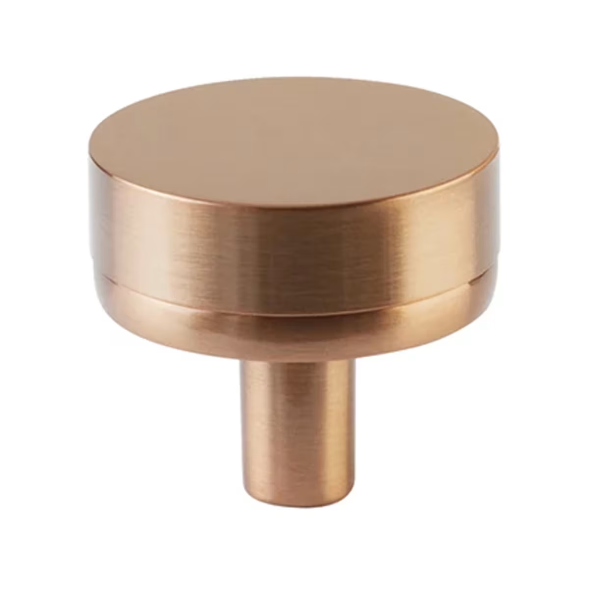
Most cabinet knob jobs arrive as a sample, a photo, or a worn original. Before any tool touches metal, the shop needs a drawing that pins down the stem diameter, the thread, the base diameter and the cap profile. For Emtek cabinet knobs CNC work, the mounting face and the stem axis are the two features everything else references. Get those wrong and the knob will sit crooked on the door no matter how good the cap looks.
Measure the original with a micrometer at three points along the stem. Check the thread with a pitch gauge, not a caliper. Common sizes land between M4 and M6, with 8–32 UNC still showing up on older American cabinets. Write the thread callout on the drawing, because a stem that is 0.1 mm under nominal will spin in the bore after plating.
Also record the base diameter and the cap height. A knob with a 20 mm base and a 32 mm cap looks balanced; scale the cap past 1.6× the base and the part tips forward under hand load. That is a design decision, but the machinist needs the number before programming.
Decide early whether the knob is a one-off replacement or a production run. A single part justifies a soft jaw and a quick setup. A 5,000-piece run justifies a custom fixture, a bar feeder and possibly a cast or forged blank. The process plan changes completely between those two cases.
- 1Measure the stem at three heightsTop, middle and where it meets the base.
- 2Gauge the threadM4 to M6 and 8–32 UNC cover most cabinet hardware.
- 3Note cap-to-base ratioUnder 1.6× keeps the knob stable in the hand.
- 4Flag one-off versus productionIt changes fixture design and blank choice.
Choosing the Material for Emtek Cabinet Knobs CNC Machining
Brass is the default. C36000 free-cutting brass machines at 200–300 m/min with carbide and leaves a finish that takes clear lacquer, nickel or black oxide without extra prep. It also takes fine detail on the cap, which matters when the original has a knurled band or a stepped edge. For most cabinet knob work, brass is the shortest path to a good part.
Stainless 303 is the fallback when the knob sees wet hands, coastal air or frequent cleaning. It machines at roughly half the speed of brass, around 100–150 m/min, and work-hardens if the tool dwells. Keep the feed per tooth up and never let the cutter rub. Stainless 316 is tougher again and only worth it if the customer specifies marine exposure.
Aluminium 6061 shows up for painted or anodized knobs and for prototypes, because it cuts fast and costs less. The trade-off is feel: an aluminium knob is light, and some buyers notice that immediately. Zinc die casting suits high volumes with simple geometry, but the tooling cost only pays back above a few thousand pieces.
Titanium and PEEK are rare here, but they appear in specialty hardware. Titanium needs slow speeds, flood coolant and sharp tools; PEEK needs a sharp edge and a high feed to avoid melting. If the drawing calls for either, expect longer programming and a test cut before the run.
- 1C36000 brass200–300 m/min, best finish and plating response.
- 2Stainless 303100–150 m/min, keep feed up to avoid work hardening.
- 3Aluminium 6061Fast and cheap, but noticeably lighter in the hand.
- 4Zinc die castingOnly pays back above a few thousand simple parts.
Five-Axis Setups That Keep the Cap and Stem Concentric
The classic failure on a curved knob is a stem that does not sit on the cap axis. Three-axis machining forces you to flip the part, and every flip adds a re-fixturing error that shows up as runout. A 16 mm simultaneous 5-axis center can cut the cap profile and the stem in one setup while the blank stays in the same vise.
Hold the blank in a soft jaw or a collet block that grips the cap diameter. Leave 3–5 mm of stock on the cap so the jaw has something to bite, and machine the stem first while the part is short and stiff. Then swing the table and cut the cap profile with a Ø6 mm ball nose, stepping over at 0.2–0.3 mm for a finish pass.
Watch the tool length. A long slender cutter in a deep cap pocket will chatter, and chatter on brass is hard to polish out. Keep the tool overhang under 4× diameter. If the cap has a deep undercut, use a Ø3 mm tool for the last pass and accept a slower feed.
For high volumes, add a Ø400 mm rotary table and run two or four knobs per cycle. The rotary table lets you index between parts without stopping the spindle, which is where the cycle time saving actually comes from.
- 1Machine the stem firstShort, stiff part, less deflection.
- 2Leave 3–5 mm on the capGives the jaw something to grip.
- 3Step over 0.2–0.3 mmBall nose finish pass on the curved cap.
- 4Keep overhang under 4× diameterLong tools chatter, and brass chatter is hard to polish.
Cutting Parameters and the Errors That Cost Parts
For C36000 brass with a 6 mm three-flute carbide end mill, run 250 m/min at 0.05 mm per tooth and a 0.5 mm depth of cut for finishing. Roughing can take 2 mm depth at the same speed. Use air blast or a light mist; brass chips clear easily and coolant just makes a mess on small parts.
Stainless 303 with the same cutter runs at 120 m/min, 0.04 mm per tooth, and you should never take a finish pass under 0.1 mm because the tool will rub and work-harden the surface. Flood coolant is required. If the chip comes off blue or the surface turns grey, stop and check the feed.
The two most common scrapped parts are an oversized stem and a torn fillet where the stem meets the cap. The stem is easy: measure with a micrometer, not a caliper, and hold the tolerance with a spring pass rather than chasing it with offsets. The fillet needs a radius that the ball nose can actually reach; a 0.5 mm fillet with a 3 mm tool is fine, but a 0.3 mm fillet is not.
Deburr in the machine where possible. A 90° chamfer tool run around the base edge saves a manual operation and keeps the chamfer consistent across thousands of parts. Hand deburring a 20 mm knob is slow and never uniform.
- 1Brass finish pass250 m/min, 0.05 mm/tooth, 0.5 mm depth.
- 2Stainless finish passNever under 0.1 mm depth; flood coolant on.
- 3Hold the stem with a spring passChasing offsets on a small diameter causes overshoot.
- 4Chamfer in the machineConsistent edge break across the whole run.
Finishing, Plating and the Order of Operations
Decide the finish before the first cut, because it changes the stock allowance. Anodizing and plating add material, typically 5–25 μm depending on the process, so a stem held exactly at nominal will be tight after plating. Machine the stem 10–20 μm under nominal when it will be plated, and confirm the thread will still gauge.
Bead blasting gives a uniform matte look and hides light tool marks. It also rounds sharp edges slightly, so mask the stem thread if the fit is close. Polishing gives the highest gloss but shows every scratch from the machining stage, which means the finish pass has to be cleaner than usual.
Brushed finishes are directional. On a curved cap, the brush lines have to follow the profile or the part looks wrong from one angle. That is a manual operation and it adds cost, so price it before quoting.
Laser marking works for logos and size codes, with a minimum character height of 1.5 mm. Below that the mark is not readable after plating. Engraving is an alternative when the mark needs depth, but it adds a tool change and a deburr step.
- 1Plating adds 5–25 μmCut the stem undersize to compensate.
- 2Bead blasting hides marksMask the thread if the fit is tight.
- 3Polishing shows everythingThe finish pass must be clean.
- 4Laser markingMinimum character height 1.5 mm.
Inspection That Catches a Bad Knob Before Shipping
A cabinet knob is a small part with tight cosmetic expectations, so inspection has to cover both dimensions and appearance. Start with the stem: diameter, thread pitch and runout relative to the cap axis. Runout above 0.05 mm shows as a wobble once the knob is on a door, even if every other dimension is in tolerance.
Check the mounting face for flatness. If the face is convex, the knob rocks on the door and the screw loosens over time. A 0.02 mm flatness check on the base is usually enough for cabinet hardware.
Then look at the cap. Measure the diameter and height, and compare the profile against the drawing with an optical comparator or a profile projector for complex shapes. Cosmetic inspection under a defined light source catches scratches, pits and uneven brush lines that a dimensional check will miss.
GreatLight runs 100% inspection before shipment, with raw material checks, in-process monitoring and a final inspection, and reports are available on request. For production runs, pull the first article, get it approved, and then sample at a defined frequency rather than inspecting every piece by hand.
- 1Stem runoutKeep under 0.05 mm to the cap axis.
- 2Mounting face flatnessAround 0.02 mm prevents rocking.
- 3Profile checkOptical comparator for curved caps.
- 4Cosmetic checkFixed light source, written accept criteria.
Step by Step: Machining a Cabinet Knob
Follow this order. Skipping a step is how parts get scrapped.
- 1Measure and draw the originalMicrometer the stem at three heights, gauge the thread, record base diameter, cap diameter and cap height. Produce a 2D drawing with the stem axis as datum A.
- 2Pick the material and blankBrass C36000 for most jobs, stainless 303 for wet or coastal use. Cut the blank 3–5 mm oversize on the cap diameter so the jaw has grip.
- 3Set up the 5-axis fixtureHold the blank in a soft jaw or collet block. Confirm the stem axis runs true to the rotary table within 0.02 mm before cutting anything.
- 4Rough the stem and cap3-flute carbide, 250 m/min at 0.05 mm/tooth for brass, 2 mm depth of cut. Leave 0.3 mm on all finish surfaces.
- 5Finish the stem, then the capStem first while the part is stiff. Spring pass to hold ±0.005 mm. Then ball nose the cap at 0.2–0.3 mm stepover with overhang under 4× diameter.
- 6Chamfer and deburr in the machineRun a 90° chamfer tool around the base edge and any sharp cap edges. Skip hand deburring where the tool can reach.
- 7Apply the finishBead blast, brush or polish as specified. Machine the stem 10–20 μm undersize before plating. Mask the thread when blasting a close-fit stem.
- 8Inspect and documentCheck stem diameter, runout under 0.05 mm, mounting face flatness around 0.02 mm, cap profile and cosmetics under fixed light. Record the results.
Material and Process Choice by Knob Type
Match the knob design to the material and machine before quoting.
| Knob type | Material | Machine | Why |
|---|---|---|---|
| Smooth round cap, plated | Brass C36000 | 5-axis, one setup | Best finish and plating response |
| Knurled band or stepped edge | Brass C36000 | 5-axis with Ø3 mm tool | Fine detail needs a small cutter |
| Wet or coastal use | Stainless 303 | 5-axis, flood coolant | Corrosion resistance, slower cut |
| Painted or anodized | Aluminium 6061 | 3-axis or 5-axis | Fast cut, light weight in hand |
| High volume, simple shape | Zinc die casting | Cast then finish machine | Tooling pays back above a few thousand |
| Deep undercut cap | Brass C36000 | 5-axis, long reach tool | Reach without re-fixturing |
| Prototype, one piece | Aluminium 6061 or brass | 3-axis with soft jaw | Cheapest path to a physical part |
One Setup Decides the Part
If the stem and cap have to stay concentric, plan for a single 5-axis setup and hold the stem with a spring pass. Three-axis flips are where cabinet knobs go wrong.
Common Questions
Can you machine a replacement for a discontinued cabinet knob?
Yes, if we have a physical sample or a drawing with the stem thread and base diameter. We measure the original, build a 2D drawing and machine a matching part.
Send the sample with the thread callout if you know it. A pitch gauge reading on the original saves a round of back-and-forth.
What tolerance can you hold on a small knob stem?
We work to ±0.005 mm on critical features and hold stem runout under 0.05 mm relative to the cap axis. Those two numbers decide whether the knob sits straight on the door.
Cosmetic features are checked against a drawing, not a tolerance number, so the accept criteria should be written down before the run starts.
How many knobs can you run, and what is the lead time?
There is no minimum order quantity. We run from one prototype to 10,000+ part runs.
Quotation and DFM analysis come back within 12 hours, production can start within 24 hours, and parts ship in 3–5 days.
Do you handle the plating and finishing as well?
Yes. Anodizing, electroless nickel, zinc, silver and gold plating, powder coating, black oxide, bead blasting, tumbling, brushing and polishing are all available.
Laser marking and engraving are available too, with a minimum character height of 1.5 mm.
Will my design details stay confidential?
Uploads are secure and confidential. We can sign an NDA on request before you send drawings or samples.
Do not send a customer logo or a trademarked shape unless you hold the rights to it. We machine what you are authorized to produce.
What do you need to quote a cabinet knob job?
A drawing or sample, the material, the finish, the quantity and the stem thread. If the knob must match an existing one, send the original.
Missing thread or finish details are the two things that slow a quote down most.
Send Your Knob Drawing or Sample
Upload a drawing or a photo of the original and we will return a quote with DFM notes within 12 hours.
12-hour quoteNo minimum order100% inspection before shipmentNDA on request
More From the Shop Floor
We publish setup notes, tooling trials and inspection data from the factory floor.











