
Drone Gyroscope Housings Machining
A gyroscope housing holds the IMU that keeps a drone level. This page explains the machining constraints behind it: material choice, datum strategy, thin-wall clamping, and what tolerance actually matters. Written for design engineers and buyers who need to judge a quote or a process.
In this article
- 1
- 2
- 3
- 4
- 5
- 6
- 7
- 8
- 9
Key takeaways
What drone gyroscope housings machining actually controls
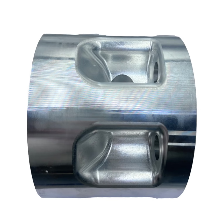
A gyroscope housing is a mechanical reference. The MEMS or fiber-optic sensor inside reports angular rate, and the flight controller trusts that reading only if the sensor sits square to the airframe. So the housing does two jobs at once: it locates the board or sensor block, and it isolates that block from vibration and stray magnetic fields.
That is why drone gyroscope housings machining is judged on geometry, not on how shiny the part looks. A bore that is 20 μm off center shifts the effective sensing axis. A mounting face that is not parallel to the reference face tilts the whole IMU. Neither shows up in a visual check, and neither is fixed by polishing.
The practical tolerance band for small UAV housings is usually ±0.005 mm to ±0.02 mm on the critical datums, with Ra 0.8–1.6 μm on sealing and mating faces. Non-critical outer surfaces can sit at Ra 1.6–3.2 μm. Splitting the drawing into critical and cosmetic zones keeps cost sane.
The second job, isolation, is a materials and mass question. Aluminum conducts heat away from the sensor fast, which is good. But it also transmits vibration, so the wall section and rib layout have to be stiff without ringing. Machining decides whether those ribs are consistent from part to part.
- 1Datum hierarchyPick one primary datum and machine every sensor face from it.
- 2Bore alignmentCoaxial bores are best cut in one continuous pass, not two setups.
- 3Wall consistencyWall thickness variation shows up as a mass imbalance in small frames.
Material selection and what it does to the cut
Most drone gyroscope housings are machined from 6061-T6 or 7075-T6 aluminum. 6061 machines cleanly, welds and anodizes well, and is the default when the housing is a simple frame. 7075 gives roughly twice the yield strength, which lets you thin the walls. It also cuts with more tool pressure and costs more per kilogram.
Magnesium AZ31B and AZ91D appear when weight is the top priority. Magnesium cuts fast and leaves a good finish, but chips are a fire risk and the material needs a coating for corrosion. Few shops run it daily. It is a real option, not a default one.
Titanium TC4 (Ti-6Al-4V) shows up in high-end and defense airframes. Its low thermal conductivity means heat concentrates at the cutting edge. Use sharp, coated tooling, high-pressure coolant, and conservative radial engagement. Letting the tool dwell in the cut work-hardens the surface and ruins the next pass.
For sensor inserts and shielding plates, 17-4PH stainless and beryllium copper are common. Stainless gives dimensional stability over temperature. Beryllium copper is used for EMI shielding because it combines conductivity with spring properties. Both are harder on tooling than aluminum and change the cycle time estimate.
- 16061-T6Default for housings and brackets; good finish, low cost, easy anodizing.
- 27075-T6Thin-wall frames where stiffness per gram matters more than price.
- 3TC4 titaniumHigh-end airframes; expect slower cuts and higher tool wear.
- 417-4PHSensor inserts that must hold size across a wide temperature range.
Five-axis setup and the fixture problem
Compound angles are the norm on gyro housings. Sensor mounting faces are often tilted 30° or 45° to the airframe axis, and the connector boss points somewhere else again. On a three-axis machine each angle needs its own setup, and each setup adds a new error to the stack.
Five-axis machining removes that stack. The part stays clamped once, and the tool tilts to reach every face. On a 16-machine five-axis floor with Ø400 mm rotary tables, a housing that measures 80 × 60 × 40 mm can be finished in two operations: one for the primary datums, one for the back side.
Thin walls are the harder problem. A typical gyro housing has 1.5–2.5 mm walls and open pockets. A standard vise squeezes the part, the walls spring inward, and the bore measures correct while clamped and wrong after release. The fix is not more clamping force. It is less.
Shops that run these parts use custom soft jaws machined to the part contour, vacuum chucks for flat frames, or low-melt fixturing for very thin sections. Some use sacrificial tabs that are cut off in a final light pass. All of these cost setup time on the first part and pay back from the second part onward.
- 1Soft jawsMachined to contour so clamping pressure spreads over a larger area.
- 2Vacuum fixturingGood for flat housings; needs a clean, flat back face.
- 3Sacrificial tabsKeeps thin floors rigid until the last operation.
Tool path choices that protect the sensor faces
The sensor mounting face is the one surface nobody wants to touch twice. Contouring passes with a constant stepover leave a uniform surface, which helps when the face is used as a datum. Plunge cuts and dwell marks do the opposite: they create local high spots that affect seating.
For aluminum, a 3-flute carbide end mill with polished flutes runs clean at 12,000–18,000 rpm in a high-speed spindle. Keep the radial engagement around 8–12% of tool diameter on finishing passes. That keeps cutting forces low and wall deflection small.
Bore quality matters as much as face quality. Reaming gives a predictable size but can follow a drilled hole that is already off axis. Boring on the five-axis, interpolated from the same datum as the faces, keeps the bore and the faces tied together. For a Ø8 H7 sensor bore, interpolation with a small-diameter end mill followed by a light ream is a common sequence.
Deburring is part of the tool path, not an afterthought. A 0.2 mm edge break on every internal pocket edge prevents chips from shedding later and keeps anodizing from building up on sharp corners. Manual deburring of a 40 mm housing is possible but inconsistent. Controlled chamfer passes are not.
- 1Constant stepover8–12% of tool diameter on finishing passes for a uniform face.
- 2Interpolated boresKeeps bore axis tied to the same datum as the mounting faces.
- 3Programmed chamfers0.2 mm edge break on internal edges, done in the cycle.
Inspection and what to measure first
A gyro housing is a small part with a dense tolerance stack, so inspection has to be planned before the first cut. The priority list is: primary datum flatness, mounting face parallelism to that datum, bore position, and bore diameter. Everything else is secondary.
On a CMM, the housing is often too small to clamp normally. A dedicated fixture that locates on the primary datum and touches nothing else gives repeatable numbers. Measuring a thin-wall housing in a standard vise tells you about the vise, not the part.
For production runs, statistical process control is more useful than 100% CMM inspection. Once the process is stable, pulling parts at intervals and charting the critical dimensions catches drift before it becomes scrap. GreatLight inspects 100% of parts before shipment, with raw material checks, in-process monitoring, and final reports on request.
Surface finish is measured on the sensor and sealing faces, not on the outside. A Ra 0.8–1.6 μm target on those faces is realistic on aluminum with the right finishing pass. Demanding Ra 0.2–0.8 μm across the whole part adds polishing time and rarely changes flight behavior.
- 1First articlesFull dimensional report on the first part of every new revision.
- 2SPC on critical dimsChart bore position and face parallelism across the run.
- 3Finish where it countsSpecify tight Ra only on sensor and sealing faces.
Post-processing and assembly fit
Anodizing adds 5–15 μm per surface depending on the process. On a Ø8 H7 bore that is a real change. If the bore is masked before anodizing, the size stays. If it is not, the shop has to cut the bore undersize to compensate. Both work, but the drawing has to say which one you want.
Hardcoat anodizing gives a wear-resistant surface on connector faces and screw bosses. Conductive anodizing keeps the housing grounded to the airframe, which matters for EMI shielding. Electroless nickel is another option when the housing needs a uniform coating on complex internal geometry.
EMI gaskets and shielding plates are usually bonded or screwed in after machining. That means the housing needs a flat, clean landing area with a controlled surface finish and no burrs. A 0.1 mm raised burr under a gasket creates a gap that leaks RF.
Assembly fit is the last check. Screw bosses should be drilled and tapped to a depth that leaves at least two full threads of engagement. Over-tapping a 1.5 mm wall is easy to do and hard to inspect. A thread depth callout on the drawing prevents it.
- 1Mask critical boresAnodizing build-up changes H7 fits unless the bore is masked.
- 2Conductive coatingKeeps the housing grounded when EMI shielding matters.
- 3Thread depth calloutPrevents over-tapping thin bosses during assembly.
Design choices that change the machining cost
The biggest cost lever is wall thickness. Above 2.5 mm, a housing can be held in soft jaws with normal feeds. Between 1.5 mm and 2.5 mm, expect custom fixturing and slower finishing passes. Below 1.5 mm, the part needs vacuum fixturing or sacrificial supports, and cycle time can double.
The second lever is tolerance distribution. Applying ±0.005 mm to every dimension on a 60 mm part forces CMM inspection on features that do not affect flight. Marking only the sensor datums as critical lets the shop run the rest at standard tolerances and inspect by sampling.
The third lever is quantity. Prototype quantities of 1–10 parts carry setup cost per unit. A 10,000-part run spreads that setup across the run and lets the shop build dedicated fixtures and inspection gauges. Volume does not lower precision; it makes holding precision cheaper per part.
For early-stage programs, it is worth machining a simplified housing first to validate the sensor mounting and the connector exit. That prototype does not need anodizing or final tolerances. It needs to fit the airframe and hold the sensor square enough to fly.
- 1Walls above 2.5 mmStandard soft jaws and normal feeds; lowest cost per part.
- 2Walls 1.5–2.5 mmCustom fixturing and lighter finishing passes; moderate cost.
- 3Walls below 1.5 mmVacuum or sacrificial fixturing; cycle time roughly doubles.
Housing material comparison for drone gyroscope housings machining
Typical values for small UAV housings up to 100 mm. Actual parameters depend on the specific geometry.
| Material | Best for | Machining behavior | Finish and coating |
|---|---|---|---|
| 6061-T6 aluminum | Default housings and brackets | Cuts fast, low tool wear | Anodizes well; Ra 0.8–1.6 μm easy |
| 7075-T6 aluminum | Thin-wall stiff frames | Higher cutting force, clean chips | Hardcoat anodizing recommended |
| AZ31B magnesium | Minimum weight airframes | Very fast cuts, chip fire risk | Needs chemical conversion coating |
| TC4 titanium | High-end and defense airframes | Slow, heat at edge, work-hardens | Bead blast; anodize possible |
| 17-4PH stainless | Sensor inserts and bosses | Difficult, needs rigid setup | Passivation or nickel plating |
| Beryllium copper | EMI shielding inserts | Abrasive, tool wear high | Silver or gold plating common |
When to choose which approach
If the housing is a simple frame with a flat IMU plate, a three-axis setup with soft jaws is enough. If it has compound sensor angles or walls under 2 mm, five-axis and custom fixturing are the only way to hold the datums. Choosing the cheaper route on a thin-wall compound part usually costs more in scrap than the five-axis cycle ever would.
Frequently asked questions
What tolerance can you hold on a small aluminum gyro housing?
On the critical sensor datums, we hold ±0.005 mm and verify on a CMM with a dedicated fixture. Non-critical outer features run at standard tolerances unless the drawing says otherwise.
The practical limit depends on wall thickness. Below 1.5 mm, spring-back during unclamping can move a bore by more than the machining tolerance, so the fixture and the inspection method both have to change.
How do you keep thin walls from deforming during machining?
We machine soft jaws to the part contour so clamping pressure spreads across a large area. For very thin floors we leave sacrificial tabs that are removed in a final light pass.
Cutting parameters matter too. Light radial engagement on finishing passes keeps cutting force low, which keeps wall deflection inside the tolerance band.
Should the sensor bore be masked before anodizing?
Yes, if the bore is a press fit or a precision clearance fit. Anodizing adds 5–15 μm per surface, which is enough to change an H7 fit.
If masking is not practical, the shop can cut the bore undersize to compensate. Either way, the drawing needs to state the finished condition after coating, not before.
What is the minimum order quantity for a prototype housing?
There is no minimum order quantity. We run from one prototype to 10,000+ part runs.
For a single prototype, expect setup cost to dominate the price. If the design is likely to change, it is usually cheaper to validate the sensor mounting on a simplified housing first.
How long does a gyro housing quote take?
Quotation and a free DFM analysis come back within 12 hours. Production can start within 24 hours after drawing release.
Parts ship in 3–5 days for standard quantities. Historical late-delivery probability is below 2%.
Can you machine magnesium and titanium housings?
Yes. We machine magnesium AZ31B and AZ91D with dedicated chip handling, and titanium TC4 with high-pressure coolant and coated tooling.
Both materials need a different cost model than aluminum. Titanium in particular runs several times slower, so the quote reflects cycle time rather than material price.
Send us the housing drawing
Upload a STEP file and a PDF drawing. We return a quote and a DFM analysis within 12 hours.
12-hour quote100% inspectionNo minimum order quantity
More from GreatLight
We publish setup notes, tooling trials and inspection data from the factory floor.











