
Drone Gimbal Parts Custom CNC Milling
A gimbal only has to do one thing: hold a camera or sensor still while the airframe shakes. Everything hard about making those parts comes from that single job. This page explains the mechanics behind drone gimbal parts custom CNC milling, where the process wins, and where it stops being the right choice.
In this article
- 1
- 2
- 3
- 4
- 5
- 6
- 7
Why gimbal geometry is hard to machine
A three-axis gimbal has to let three motors push a payload in roll, pitch and yaw while the airframe moves underneath it. That means the moving parts must be stiff in the load direction and light everywhere else. The two requirements pull against each other, and the part geometry is where they meet.
The usual shape is a thin-walled housing with pockets, an internal wiring channel, a bearing bore and a motor mounting face that has to sit square to the rotation axis. A typical camera gimbal arm sits between 1.2 mm and 2.5 mm wall thickness. Below roughly 1.0 mm, cutting forces start pushing the wall instead of cutting it.
Balance is the other constraint. An imbalance of 0.5 g·mm on a small roll axis is enough to make the motor hunt at low speed, which shows up as jitter in the footage before it shows up on any drawing. Milling lets you remove material in measured steps and then trim to a target mass, which is why most gimbal structural parts are milled rather than cast or molded.
None of this is exotic. It is just unforgiving. A general machine shop can hit the drawing on one part and miss it on the next one because the wall deflects differently as the tool wears.
Which gimbal parts suit drone gimbal parts custom CNC milling
Milling fits parts with three traits: several faces that must be related to each other, moderate to tight tolerances, and a low to medium quantity. Yokes, roll arms, pitch brackets, motor mounts, camera cages, bearing housings and damping plate interfaces all fall into this group.
The reason is setup count. A yoke with a bearing bore on one side and a motor face on the other has to be machined in one setup, or two setups that reference each other precisely. On a 5-axis machine the part can be cut from five sides, including the underside of the upper arm, without a second fixture. That removes the stack-up error you get when you flip a part and re-datum it.
Material choice follows the same logic. 7075-T6 aluminium is the default for arms and yokes because its strength-to-weight ratio lets you keep the wall thin. 6061-T6 is cheaper and easier to anodize, so it goes on brackets and housings where stiffness matters more than minimum mass. TC4 (Ti-6Al-4V) shows up on heavy-lift and industrial gimbals where the arm sees real vibration load, and carbon fibre or PEEK appears on parts that must stay electrically neutral near an antenna.
The limit is quantity and shape. Once a gimbal frame is a single hollow shell, or the annual volume runs into tens of thousands of identical parts, milling stops competing with die casting or injection molding on unit cost. It still wins on tooling lead time and on design changes, because there is no mold to cut.
Tolerances, wall thickness and surface finish that actually matter
The tolerance callout on a gimbal drawing should be split. Bores that carry bearings, and the mating faces that define the rotation axes, need the tight band. Outer profile, pockets and cosmetic surfaces do not. Marking everything at ±0.005 mm doubles inspection time and cost for no gain in stability.
For bearing bores, ±0.005 mm is our standard achievable band, with the bore roundness and the perpendicularity to the mounting face controlled at the same time. For a typical 6800-series bearing seat on a small gimbal, that is the difference between a press fit that holds preload and one that lets the axis wobble a few thousandths of a degree.
Wall thickness is a process question, not a drawing question. A 1.0 mm wall in 7075 is machinable with light radial cuts and a sharp tool. A 0.6 mm wall in the same alloy needs reduced depth of cut, more passes and probably a support fixture, and it will still move after the vise releases. If the design can tolerate 1.5 mm, take it.
Surface finish matters where a part slides or where light scatters. Bearing bores usually land at Ra 0.8–1.6 μm, and seal or damping interfaces can go to Ra 0.2–0.8 μm. Cosmetic external surfaces are typically Ra 1.6–3.2 μm before anodizing, because anodizing adds a slight texture of its own.
- 1Tight bandBearing bores and axis-defining faces: ±0.005 mm
- 2Open bandProfiles, pockets, non-mating surfaces: ±0.05 mm is usually enough
- 3Wall floor1.0 mm in aluminium without special support; thinner needs a fixture plan
- 4Bore finishRa 0.8–1.6 μm for bearing seats, Ra 0.2–0.8 μm where a seal runs
Balance and inertia: where milling decisions show up in flight
A gimbal motor fights inertia and imbalance. Inertia is set by mass and by how far that mass sits from the axis. Imbalance is set by how evenly the mass is distributed around the axis. Milling affects both, and it does so on every part, not just on the first article.
Inertia is the reason pockets exist. Removing 8 g of aluminium from a roll arm at a 40 mm radius cuts the moment of inertia far more than removing the same 8 g from the hub. A machined pocket, placed correctly, buys motor bandwidth. That bandwidth is what lets the gimbal hold a horizon during a fast yaw input.
Imbalance is the reason two parts from the same drawing must weigh the same. If the left arm is 12.4 g and the right arm is 12.9 g, the controller corrects a constant offset every cycle. At low motor speed this appears as a slow drift; at high speed it eats into the correction budget that should be damping airframe vibration.
In practice we control this by milling symmetric parts as a pair from the same billet batch, checking mass on a scale with 0.01 g resolution, and trimming in a finishing pass rather than leaving the difference to the anodizing line. Anodizing removes and adds a few micrometres, which is not enough to fix a 0.5 g mismatch.
What the machine setup has to look like
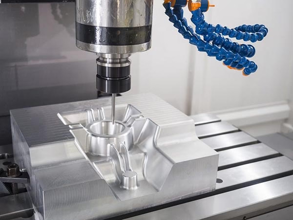
Gimbal work is 5-axis work. The 16 simultaneous 5-axis machining centers in our shop handle the concave side of a yoke, an undercut motor mount and a slanted bearing face in a single setup. Our 4-axis and 3-axis machines still take the simpler brackets, spacers and adapter plates where the geometry is open on one side.
A Ø400 mm rotary table covers most gimbal yokes and camera cages. For larger industrial gimbal frames, the work envelope goes up to 4,000 mm of travel, which is relevant for long arms on survey and inspection payloads. Thin-wall parts are usually run on dedicated soft jaws or a vacuum plate so the clamping force does not distort the bore.
Inspection is where the process either holds or falls apart. Bores are checked with a bore gauge or CMM, not with calipers. Wall thickness is checked with an ultrasonic gauge on closed sections. Mass is checked on a scale. Every part is inspected before shipment, and reports are available on request.
The reason this level of setup matters is repeatability. A single ±0.005 mm part proves nothing. A 500-part run where every bore stays inside that band is what keeps a gimbal from hunting.
When milling is the wrong process
Milling is a subtraction process with a tool that needs to reach the cut. If a gimbal housing has a closed internal cavity with no access, or a wiring channel that turns 90° inside the part, no end mill gets there. Those features belong to die casting, additive manufacturing or a split-and-bolt design.
Cost crosses over with volume. A machined gimbal arm is economical from one piece to a few thousand a year. At 10,000 identical units, die casting or molding usually wins on unit price, even after you pay for tooling. The trade is that a design change then costs a new mold instead of a new program.
Milling also has a size floor. A part with walls below about 0.5 mm in metal is better made from sheet metal, or molded in a carbon-fibre-reinforced plastic, than machined. The machining forces and the residual stress release will move the part no matter how light the cuts are.
One more boundary: material. Soft, gummy plastics and very hard tool steels are both possible, but they change feeds, speeds and tool life. If your gimbal frame is PEEK or a carbon-fibre composite, the machining strategy is closer to a composite operation than to aluminium.
Process and material selection for gimbal parts
Pick the row that matches your part, not the row with the best numbers.
| Part | Best process | Typical material | Why |
|---|---|---|---|
| Roll/pitch yoke with bearing bores | 5-axis milling | 7075-T6 | Two related faces in one setup |
| Motor mount bracket | 4-axis or 3-axis milling | 6061-T6 | Open geometry, moderate tolerance |
| Camera cage, thin walls | 5-axis milling + soft jaws | 7075-T6 or carbon fibre | Mass trim and wall control |
| Damping plate interface | 3-axis milling | 6061 or 5052 | Flat, simple, cheap to inspect |
| Heavy-lift gimbal arm | 5-axis milling | TC4 (Ti-6Al-4V) | Vibration load, stiffness |
| Closed hollow housing | Die casting | ADC12 or magnesium | No tool access for milling |
| 10,000+ identical frames | Die casting or molding | ADC12, PA, PEEK | Mold amortizes at volume |
The verdict
If your gimbal needs related faces held inside ±0.005 mm and the annual volume is under a few thousand pieces, drone gimbal parts custom CNC milling on 5-axis equipment is the right call. If the part has a closed internal cavity or the volume runs past 10,000 identical units, design for casting or molding instead and machine only the critical interfaces.
Questions engineers ask before quoting
How tight a tolerance can you hold on a gimbal bearing bore?
Our standard achievable band is ±0.005 mm (±0.0002 in) on bores and axis-defining faces, measured on a CMM or bore gauge rather than calipers.
That band only makes sense on the features that set the rotation axis. Putting the same callout on an outer profile adds inspection time without improving stability, so we usually suggest splitting the tolerance on the drawing.
What wall thickness can you mill in 7075-T6?
Around 1.0 mm is a practical floor on a normal gimbal arm, using light radial cuts and a sharp tool. At 0.6–0.8 mm the part needs reduced depth of cut, more passes and probably a support fixture, and it may still move after unclamping.
If the design has room, 1.5 mm buys a much more stable process for a small mass penalty.
Can you match the mass of left and right gimbal arms?
Yes. We mill symmetric pairs from the same billet batch and check mass on a 0.01 g scale, then trim in a finishing pass. That keeps the two arms within a fraction of a gram of each other.
Anodizing removes and adds only a few micrometres, so it cannot correct a mass mismatch. The correction has to happen at the machine.
Do you machine PEEK or carbon-fibre gimbal parts?
We machine PEEK, ABS, PC, POM, PA, PP and carbon fibre, and we also machine magnesium AZ31B and AZ91D where mass is critical.
These materials change the cutting strategy. Carbon-fibre composites need diamond-coated tooling and dust control; PEEK needs sharp edges and controlled heat. The geometry is the same, the parameters are not.
What is the smallest quantity you will run?
There is no minimum order quantity. We run from one prototype to 10,000+ piece runs on the same equipment and the same inspection process.
For a single prototype we would usually suggest milling the critical interfaces so the first flight test reflects the real part, not a substitute.
How fast can we get a quote and parts?
Quotation and a free DFM analysis come back within 12 hours. Production can start within 24 hours of a released drawing, and parts ship in 3–5 days.
Uploads are secure and confidential, and we can sign an NDA before you send drawings.
Send the drawing, get a DFM answer
Upload your gimbal part and we will tell you within 12 hours whether the geometry machines cleanly, which features need a tighter band, and where the mass can come out.
12-hour quoteFree DFM analysis100% inspectionNDA on request
More machining notes
We publish setup notes, tooling trials and inspection data from the factory floor.











