When cutting metal, the tool cuts the workpiece and the tool angle is an important parameter used to determine the geometry of the cutting part of the tool.
1. Composition of the cutting part of the turning tool
Three sides, two edges and a point
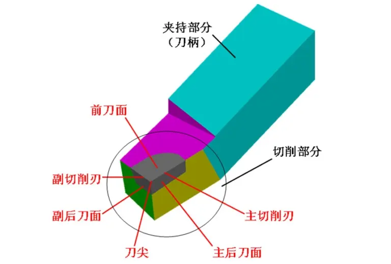
The cutting part of the turning tool includes the cutting surface, the main flank surface, the auxiliary flank surface, the main cutting edge, the auxiliary cutting edge and the tool tip.
1) Cutting face: the surface of the tool where the chips flow.
2) Main flank surface The surface of the tool which faces and interacts with the machined surface of the workpiece is called main flank surface.
3) Secondary flank surface The surface of the tool which faces and interacts with the machined surface of the workpiece is called secondary flank surface.
4) Main cutting edge The line of intersection between the rake face and the main flank face of the tool is called the main cutting edge.
5) Secondary cutting edge The line of intersection between the rake face and the secondary flank surface of the tool is called secondary cutting edge.
6) Tool tip The point of intersection between the main cutting edge and the auxiliary cutting edge is called the tool tip. The tool tip is actually a small curve or straight line, called rounded tool tip and chamfered tool tip.
2. Auxiliary plane for measuring the cutting angle of turning tools
In order to determine and measure the geometric angle of the turning tool, three auxiliary planes should be selected as reference. These three auxiliary planes are the section plane, the base plane and the orthogonal plane.
1) Cutting plane – a plane that cuts at a selected point on the main cutting edge and is perpendicular to the lower plane of the tool holder.

2) Base surface – a plane passing through a selected point of the main cutting edge and parallel to the bottom surface of the tool holder.

3) Orthogonal plane – a plane perpendicular to the section plane and perpendicular to the base plane.

It can be seen that these three coordinate planes are perpendicular to each other and form a rectangular spatial coordinate system.
3. Main geometric angles and selection of turning tools
1) Principles of cutting angle selection (γ0)
The size of the cutting angle mainly solves the conflict between the sturdiness and sharpness of the cutter head. Therefore, the cutting angle should first be selected according to the hardness of the material to be processed. If the hardness of the processed material is high, the cutting angle should take a small value, otherwise it should take a high value. Secondly, the cutting angle should be considered based on the machining properties. The cutting angle should be a low value when rough machining and a high value when finishing. The cutting angle is generally chosen between -5° and 25°.

Usually, when manufacturing turning tools, the cutting angle (γ0) is not preset, but the cutting angle is obtained by sharpening the chip groove on the turning tool. The chip flute is also called a chip breaker. Its function is to break the chips without causing entanglement, control the chip flow direction to maintain the precision of the machined surface and extend the tool life;

2) Principles of selection of the draft angle (α0)
Let’s first consider the processing properties. During finishing, the draft angle takes on a greater value; during rough machining, the clearance angle takes a smaller value. Second, consider the hardness of the material being processed. If the hardness of the processed material is high, the main clearance angle should be small to improve the strength of the tool head. Conversely, the draft angle should be low. The draft angle cannot be zero or negative, and is generally chosen between 6° and 12°.

3) Principles of selection of the main deflection angle (Kr)
First, consider the rigidity of the turning process system consisting of lathes, fixtures, and tools. If the rigidity of the system is good, the angle of attack should be small, which will help to increase the life of the turning tool and improve the heat dissipation conditions. and surface roughness. Secondly, the geometric shape of the room must be taken into account. During the processing stages, the main declination angle should be 90°. When processing parts cut in the middle, the main declination angle should generally be 60°. The main deflection angle is generally between 30° and 90°, with the most commonly used being 45°, 75° and 90°.

4) Principle of selection of the secondary declination angle (Kr’)
First, consider that the turning tool, workpiece, and fixture have sufficient rigidity to reduce the secondary deflection angle; otherwise, a larger value must be taken. Second, consider processing properties. When finishing, the secondary deflection angle can be between 10° and 15°. °, and when roughing, the secondary declination angle can be around 5°.

5) Principle of selection of the edge inclination angle (λS)
It mainly depends on the machining properties. During rough machining, the workpiece has a large impact on the turning tool, so λS ≤ 0°. During finishing, the part has a low impact on the turning tool, therefore λS ≥ 0°; λS =0°. The blade inclination angle is generally chosen between -10° and 5°.

Daguang focuses on providing solutions such as precision CNC machining services (3-axis, 4-axis, 5-axis machining), CNC milling, 3D printing and rapid prototyping services.


