
Dental Implant Abutment CNC Machining
An abutment is the part that carries occlusal load from a crown into the implant fixture, so its geometry decides whether the screw stays tight and the soft tissue stays sealed. This page explains how dental implant abutment CNC machining actually works, where the process limits sit, and which part geometries belong on a mill and which do not.
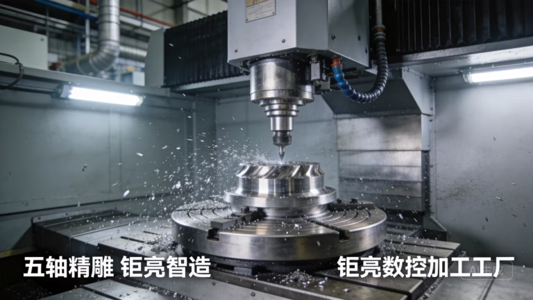
What an abutment has to do mechanically
An abutment screws into the implant platform, passes through the gum, and gives the crown a place to sit. Three jobs happen on one small part: it must seal against the implant interface so oral fluid cannot reach the internal thread, it must hold screw preload without loosening under cyclic load, and it must shape the tissue opening so the gum heals against a smooth, correctly angled surface.
That combination is why tolerances tighten fast. A flat screw seat that is out of square by a few microns turns into uneven contact, and uneven contact bleeds preload. Once preload drops, micromotion appears at the implant-abutment junction and the joint starts to leak and eventually fatigue.
The interface itself is a matched pair. The implant is made on its own line, often to a different tolerance band. The abutment has to fit parts it will never touch during inspection, so the drawing usually controls the interface dimensions rather than the whole part.
- 1Screw seat flatnessDrives how much of the torque becomes clamping force.
- 2Platform fitControls the gap at the implant-abutment junction.
- 3Emergence profileSets how the gum seals around the transmucosal section.
Why abutment geometry pushes toward 5-axis
A stock abutment is mostly a turned part. A custom abutment is not. The screw channel is often angled 15° to 25° off the implant axis to bring the access hole out through the occlusal surface instead of the facial wall. The counterbore at the bottom of that channel has to sit square to the channel, not to the part axis.
At the same time the transmucosal section carries a series of non-linear curves that follow a scanned emergence profile, and the supragingival section is reduced to a wall thickness that leaves room for the crown material. A 3-axis mill can reach the top, but it cannot keep the tool normal to a curved surface while also reaching into an angled bore.
On a 3-axis machine the usual workaround is to reposition the part two or three times. Each repositioning leaves a witness line where the passes meet, usually right across the emergence profile. Hand polishing that line out changes the geometry you spent the CAM time creating.
- 1Angled screw channelNeeds the tool axis to follow the bore, not the part axis.
- 2Curved emergenceContinuous tool-to-surface angle avoids witness lines.
- 3Single setupFewer re-clamps, less stack-up error on the interface.
Titanium grades: biocompatibility against machinability
Grade 4 commercially pure titanium and Ti-6Al-4V (TC4) cover most abutment work. Grade 4 is softer, machines with less tool wear, and is a common choice for one-piece and transmucosal sections where the part will contact tissue directly. Ti-6Al-4V is roughly twice the yield strength and is used where the wall section is thin or the abutment carries a cantilevered crown.
Both are poor conductors of heat. Titanium conducts heat away from the cut slowly, so the heat goes into the tool edge. Run a titanium part with the speeds and feeds from an aluminum job and the edge will round over within a few minutes, which shows up as a torn surface and a drifting diameter.
Chips are the other issue. Titanium tends to smear rather than break cleanly. Sharp, uncoated or lightly coated carbide, high-pressure coolant aimed at the cutting zone, and a feed rate that keeps the edge cutting rather than rubbing all matter more than spindle speed does.
- 1Grade 4 TiBetter machinability, used for tissue-contact sections.
- 2Ti-6Al-4VHigher strength for thin walls and cantilevered crowns.
- 3Heat controlCoolant at the edge and feeds that avoid rubbing.
Surface finish: where biology sets the limit
The transmucosal zone is the part the gum attaches to, and it is usually specified between Ra 0.2 μm and Ra 0.8 μm. Below that range the surface is smooth enough that there is nothing for tissue to grip. Above it, plaque retention climbs. Machined surfaces in the Ra 1.6–3.2 μm band belong on the screw interface and hidden faces, not on tissue-contact surfaces.
Getting a fine finish on a curved surface is not the same as getting it on a flat one. The finish is produced by the last pass, so the toolpath has to keep constant engagement along the curve. If the stepover widens in a tight radius, the finish changes with position and the report shows a range instead of a number.
Deburring matters just as much. A burr at the screw seat or the platform edge will hold the joint open by the height of the burr. On abutments, deburring is done with controlled hand tools and magnification rather than a tumbler, because a tumbler is not selective about which edges it rounds.
- 1Tissue contactTarget Ra 0.2–0.8 μm, measured on the actual curve.
- 2Hidden facesRa 1.6–3.2 μm as machined is normally acceptable.
- 3DeburringControlled edges at the seat and platform, not tumbling.
How abutments are inspected and qualified
The interface is the first thing measured. The platform diameter, the internal connection geometry, and the screw seat height are checked against the drawing before anything else on the part. If the seat is off, the rest of the part does not matter.
Optical or video measurement handles the profile and the screw channel angle. Contact measurement handles the seat flatness and the surfaces the crown will bond to. The screw channel angle is usually confirmed with the abutment seated on a gauge fixture rather than on the bare part, because the angle only matters in the assembled position.
For a medical part, inspection records follow the lot. GreatLight holds ISO 13485:2016 alongside ISO 9001:2015, IATF 16949:2016, and ISO 27001:2022, and runs 100% inspection before shipment with raw material checks, in-process monitoring, and a final pass. Reports are issued on request.
- 1Interface firstPlatform, connection, and seat height before profile.
- 2Angle in positionScrew channel checked seated on a gauge fixture.
- 3Traceable recordsInspection data kept with the lot, reports on request.
When milling an abutment is the right call
Match the geometry and volume to the process, not the other way around.
| Scenario | Best process | Why |
|---|---|---|
| Custom angled screw channel | 5-axis CNC | Single setup, tool follows the bore axis |
| Straight stock abutment, high volume | CNC turning | Axisymmetric, fast cycle, tight diameter control |
| Patient-specific emergence profile | 5-axis CNC | Curved surface finished in one continuous pass |
| Lattice or porous tissue scaffold | Additive, then finish | Internal voids are not reachable by a cutter |
| Bar with multiple abutment stations | 5-axis CNC | Positional accuracy across the full span |
| One-off concept fit check | CNC prototype | Real material properties before tooling spend |
The short version
If the part has an angled screw channel or a patient-specific emergence profile, mill it on 5 axes in one setup. If it is a straight axisymmetric stock abutment in volume, turn it. Additive only makes sense when the geometry has internal features a cutter cannot reach.
Questions engineers ask before releasing the drawing
What tolerance should the screw seat actually carry?
The seat flatness and its squareness to the screw channel are the two dimensions that convert torque into clamping force. Loose bands here show up as loosening screws long before any dimensional check fails.
In practice we hold ±0.005 mm on the critical interface features and keep the seat reference tied to the channel axis, not to the outside diameter of the blank.
Can a 3-axis machine hold an angled screw channel?
It can reach a shallow angle with a long tool, but the seat will not be square to the channel unless the part is repositioned. Each reposition adds stack-up error at the interface.
For angles above roughly 10°, the setup time and the rework risk usually exceed the cost difference of running the part on a 5-axis center.
Does the finish have to be uniform over the whole part?
No. The tissue-contact zone needs the fine range, and hidden faces or the screw interface do not. Specifying one finish everywhere raises cycle time without improving the fit.
Mark the tissue-contact band on the drawing with its own surface callout so the CAM stepover can be set per region.
How do we handle the implant side of the interface?
Send the mating implant drawing or a gauge. The abutment is checked seated against that reference, because measuring the part alone does not tell you whether the pair closes.
If the implant is proprietary, a functional gauge is the only reliable route and it needs to be in the inspection plan from the start.
What volumes make sense before tooling up?
There is no minimum order quantity here, so a single prototype and a 10,000-part run sit on the same process route. Prototyping first is usually cheaper than cutting a dedicated fixture on a drawing that has not been fit-checked.
Production can start within 24 hours of a released design, and parts normally ship in 3–5 days.
Which documents come with the shipment?
Inspection reports, material certificates, and certification copies are available on request. Raw material is checked on receipt, dimensions are monitored during the run, and every part gets a final inspection before it ships.
Uploads and drawings are treated as confidential, and an NDA can be put in place before files are shared.
Send the abutment drawing and the mating implant spec
We review geometry, material, and interface tolerance together, then quote and return a DFM analysis within 12 hours. Three plants in Dongguan and Singapore, 127 CNC machines, 16 of them simultaneous 5-axis.
12-hour quote100% inspectionISO 13485:2016No MOQ
More process notes
We publish setup notes, tooling trials and inspection data from the factory floor.











