
Exterior Circle Contours Milling Programming: Complete Guide to Round Profiles
This page explains how exterior circle contours milling programming works on real shop floors: how the path is built, what the tool does at each pass, and where the method stops being the right choice. It is written for engineers and buyers who need to judge a round part before it is quoted.
In this article
- 1
- 2
- 3
- 4
- 5
- 6
- 7
What exterior circle contours milling programming actually controls
A round outer profile looks simple on a drawing. In the control it is a chain of decisions: how the cutter enters, how it holds radial engagement around the arc, and how it leaves without leaving a witness mark. Exterior circle contours milling programming is the set of instructions that turns a diameter callout into those motions. The part may be a flange, a spool, a rotor hub, or a bushing shoulder.
The contour is only one feature on that part. The programmer still has to respect the stock left by the previous operation, the fixture that holds the blank, and the direction the tool can safely exit. A clean arc in CAD can become a chatter line on the machine if the radial depth of cut is wrong for the tool.
Most failures on round profiles are not geometry errors. They come from entry style, tool engagement, or a fixture that lets the part move under load. The code may be mathematically correct and still produce an out-of-round part. That gap between correct code and correct part is what this page covers.
- 1Arc toleranceThe control splits a full circle into small linear moves when the arc tolerance is loose, and the flats show up on a CMM trace.
- 2Entry and exitA tangential arc entry spreads the load; a straight plunge leaves a mark at the start point.
- 3Radial engagementKeeping the cutter engaged over a consistent arc of contact controls load and heat.
Why a circle is harder to mill than a straight edge
On a straight wall, the cutter sees a constant radial engagement and a constant chip load. On an exterior circle, the contact arc changes as the tool moves around the profile. On the outside of the circle, the cutter sweeps a convex surface and the engagement angle varies with the tool diameter relative to the part radius.
When the tool diameter is small compared with the part radius, engagement stays close to a straight cut and the load is predictable. When the tool is large relative to the radius, the contact arc grows and the load climbs. A Ø20 mm end mill cutting a Ø30 mm boss is working near the limit of what a light finishing pass can hold.
This is why exterior circle contours milling programming usually uses a smaller cutter than a straight-wall operation would. The smaller tool keeps engagement stable around the arc. The trade is more passes and more path length, which the programmer accepts because the surface and the roundness are worth it.
The same logic applies to climb versus conventional milling. Climb milling on an exterior contour pulls the tool into the cut and gives a better finish on most materials, but it needs a machine with low backlash. On an older mill with worn ball screws, conventional milling may hold the profile more consistently.
How to build the exterior contour path step by step
Start with the finished diameter and work backward. Add the finishing allowance, usually 0.2–0.5 mm on the radius for steel and 0.1–0.2 mm for aluminum. That allowance is what the finishing pass removes, so it must be uniform around the whole arc or the finish pass will cut unevenly.
Set the entry as a helical or tangential arc, not a straight plunge. A tangential entry lets the cutter reach the profile at full feed without a dwell mark. On a Ø50 mm boss, an entry arc radius of 10–15 mm is a common starting point. The exact value depends on the tool diameter and the space around the part.
Build the roughing passes with a constant radial stepover. A stepover between 40% and 60% of the tool diameter keeps the chip load stable on most materials. If the part is thin-walled, drop the stepover and increase the number of passes instead of increasing the cut depth.
Finish the profile in one continuous motion where possible. Stopping mid-arc leaves a witness mark that a CMM will pick up as a roundness error. If the tool must stop, place the stop at a point that will be covered by a later operation or a non-critical surface.
- 1Finishing allowance0.1–0.5 mm on radius, uniform around the full circle.
- 2Entry typeHelical or tangential arc, never a straight plunge on a finished profile.
- 3Stepover40–60% of tool diameter for stable radial engagement.
Mill-turn versus pure mill for exterior circle contours
A mill-turn center can turn the outside diameter and mill the contour features in one setup. For a round part with slots, flats, or cross-holes, that saves a second operation and removes the error from re-chucking. The part stays on the same axis, so the exterior circle contour is concentric with the turned features by construction.
A pure mill can do the same profile, but the part usually has to be indexed or re-fixtured. Each re-fixture adds a setup error. On a part with a roundness callout tighter than 0.02 mm, that error can be larger than the tolerance. The mill-turn route holds the relationship between the bore and the outer profile without a second setup.
The trade is access. A mill-turn center has more of the part inside the spindle, so deep pockets or features on both ends may need a separate mill op. For a simple round flange with a milled hex or a keyway, the mill-turn path is usually faster and more accurate. For a complex housing with features on five faces, the pure mill or a 5-axis center is the better route.
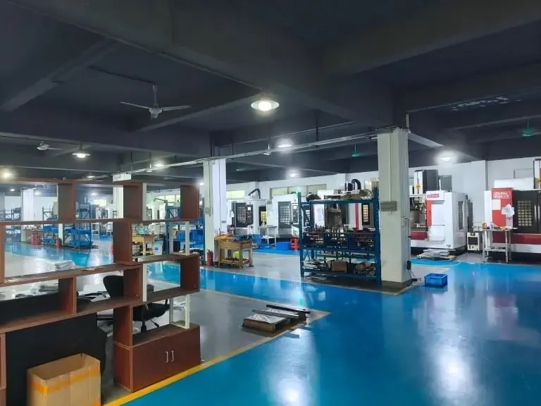
At GreatLight, the 16 mill-turn centers handle round parts up to Ø400 mm on the rotary table, and the 16 simultaneous 5-axis centers cover parts that need access from multiple directions. The choice is made per part, not per shop.
What tolerance and finish exterior circle contours milling programming can hold
On a rigid setup with a sharp tool and a stable cut, exterior contours can hold ±0.005 mm on diameter and Ra 0.8–1.6 μm on the finished surface. That is the working range for most aluminum and stainless parts. A finer finish, Ra 0.2–0.8 μm, needs a dedicated finishing pass with a small stepover and a fresh insert or end mill.
Roundness is a separate callout from diameter. A part can be on size and still be out of round. The usual causes are an uneven finishing allowance, a fixture that lets the part spring, or a tool that deflects as it goes around the arc. Measuring roundness on a CMM or a roundness tester is the only way to know which one is happening.
Wall thickness matters more than diameter on thin-wall parts. A round section under 2 mm wall will deflect under cutting load unless the radial depth is reduced and the part is supported. In those cases, a light finishing pass at low feed per tooth often holds the profile better than a heavy roughing pass.
Inspection is 100% before shipment at GreatLight, with raw material check, in-process monitoring, and final inspection. For round profiles, that means the diameter, the roundness, and the surface finish are all checked against the drawing before the part leaves the floor.
Choosing the cutting method for a round exterior profile
Tool diameter is measured relative to the finished part radius.
| Condition | Method | Typical result |
|---|---|---|
| Tool Ø ≤ 30% of part radius | Full contour in one roughing pass | Stable load, good chip evacuation |
| Tool Ø 30–60% of part radius | Two-pass rough and finish | Balanced cycle time and roundness |
| Tool Ø > 60% of part radius | Light radial passes, small stepover | Lower cutter load, longer cycle |
| Part held in a 3-jaw chuck only | Add tailstock or steady rest | Less deflection, tighter roundness |
| Thin-wall round section | Reduce radial depth, climb mill | Less distortion, better finish |
| Hardened steel above 45 HRC | Small stepover, lower feed per tooth | Tool life preserved, finish held |
| Aluminum 6061 or 7075 | Higher feed, climb mill | Ra 0.8–1.6 μm achievable |
Mill-turn vs. pure mill for round exterior profiles
Both methods can hold the same tolerance on a simple round flange. The difference shows up on parts with multiple features.
| Factor | Mill-turn | Pure mill |
|---|---|---|
| Setups for a round part | One | Two or more |
| Concentricity of bore to OD | Held by machine geometry | Depends on fixture accuracy |
| Roundness on thin walls | Better, less re-chucking | More risk of distortion |
| Access to both ends | Limited by spindle | Better with a 4th axis |
| Cycle time on simple flanges | Shorter | Longer |
| Ideal part type | Round with slots or flats | Complex housing, 5-face work |
When to choose which method
If the part is round with slots, flats, or cross-holes and needs tight concentricity, choose mill-turn and program the exterior circle contour in the same setup. If the part has deep pockets, features on five faces, or a geometry that will not fit inside the spindle, choose a 5-axis mill and accept the extra setup.
Questions engineers ask about exterior circle contours
Can exterior circle contours milling programming hold a roundness callout tighter than the diameter tolerance?
Yes, but roundness depends on the finishing allowance and the fixture, not just the code. A uniform allowance and a rigid setup are what make the roundness callout achievable.
If the part is thin-walled or held in a 3-jaw chuck only, expect roundness to be looser than the diameter callout. Adding a tailstock or steady rest usually fixes it.
What tool diameter should be used for a round exterior profile?
A tool diameter around 30–60% of the part radius keeps radial engagement stable around the arc. Below 30%, the cut is predictable but the cycle time grows. Above 60%, engagement and load climb quickly.
The exact value depends on the material and the wall thickness. On hardened steel, go smaller to protect tool life.
Why does the finish look different at the start and end of the contour?
That is almost always an entry or exit mark from a straight plunge or a stop mid-arc. A tangential or helical entry spreads the load and removes the mark.
If the mark persists, check the finishing allowance. An uneven allowance leaves more material in one section, and the finish pass cuts deeper there.
Is climb milling always better on an exterior circle?
On a machine with low backlash and a rigid setup, climb milling gives a better finish and longer tool life on most materials.
On an older machine with worn ball screws, conventional milling may hold the profile more consistently because the tool is not pulled into the cut.
How does exterior circle contours milling programming change for a thin-wall part?
Reduce the radial depth of cut and increase the number of passes. A light finishing pass at low feed per tooth holds the profile better than a heavy roughing pass.
Support the part with a steady rest or fill the bore if the wall is under 2 mm.
What materials can GreatLight run exterior circle contours on?
Aluminum 6061, 7075, and 2024; stainless 303, 304, 316, and 17-4PH; steel 1018, 1045, and 4140; titanium TC4; and engineering plastics including POM, PEEK, and ABS.
The cutting parameters change with the material, but the path strategy for the exterior circle contour stays the same.
Send us a round part and get a quote in 12 hours
Upload your STEP file and drawing. We review the exterior circle contour, the fixture, and the tolerance before we quote. Quotation and a free DFM analysis come back within 12 hours.
12-hour quote100% inspectionNo minimum order quantity
More CNC process notes
We publish setup notes, tooling trials and inspection data from the factory floor.











