
CNC Turning Savannah: How the Process Works
A working explanation of CNC turning for engineers and buyers sourcing parts for Savannah-area programs. We cover how a single-point tool removes material, which features belong on a lathe and which do not, how tolerance and surface finish are controlled, and how to read a turning quote.
In this article
- 1
- 2
- 3
- 4
- 5
- 6
What CNC Turning Savannah Shops Actually Do Inside the Machine
CNC turning removes material with a single-point insert while the workpiece spins. The turret indexes to a new tool, the controller moves it along X and Z, and a new diameter or face is cut. That is the whole idea, and it holds true whether the machine is a two-axis lathe or a current mill-turn center.
Part geometry comes from the path of the tool tip, not from the shape of the cutter. A lathe can cut any diameter it can reach, so one program covers a family of sizes. A mill needs a cutter matched to each pocket and corner radius, which is why small internal radii get expensive fast on a milling machine.
Cutting speed is set by surface speed at the outer diameter, in m/min. A Ø20 mm bar at 200 m/min spins near 3,180 rpm. A Ø200 mm flange at the same surface speed turns at about 318 rpm. Same insert, very different spindle load.
Feed per revolution controls chip thickness and surface finish. On aluminum, 0.15–0.30 mm/rev with a 0.8 mm nose radius gives Ra 0.8–1.6 μm in a stable setup. Drop the feed too low and the insert rubs instead of cutting, which shortens tool life and smears the finish.
Which Features Belong on a Lathe, and Which Do Not
Turning is the right process for anything that is fundamentally round: shafts, bushings, spacers, pistons, valve bodies, threaded studs, flanges with a bolt circle. If the part can be defined by a series of diameters along one centerline, turning is usually the cheapest and most accurate way to make it.
The trouble starts with features that run across the axis. A cross-drilled hole at 90° to the centerline, a slot on a flange face, or a hex on the end of a shaft all need a second operation unless the machine has live tooling. On a plain two-axis lathe, each of those becomes a separate setup, and each setup adds cost and stack-up error.
Mill-turn centers solve most of that. GreatLight runs 16 mill-turn centers alongside 16 simultaneous 5-axis machining centers. On a mill-turn machine, the B-axis or a driven tool reaches the part while it is still clamped, so a cross hole and a face slot can come off in the same cycle. That removes two fixtures and the error that comes with them.
Deep bores are the other boundary. A bore deeper than 4× its diameter starts to deflect the bar and the boring bar. Past 6×, chip evacuation gets unreliable and the finish breaks down. If your drawing calls for a Ø10 mm bore 120 mm deep, expect to discuss gun drilling instead of standard turning.
Thin walls are a similar story. A tube with a 0.5 mm wall will move under chuck pressure no matter how good the program is. We switch to soft jaws, a collet, or a mandrel, and sometimes plan a semi-finish pass with a stress-relief pause between roughing and finishing.
How ±0.005 mm Is Held, and When It Is Not Needed
A tolerance is a number on a drawing. Holding it is a matter of thermal stability, tool wear and machine geometry. A lathe that cuts a Ø30 mm journal at ±0.005 mm on Monday morning will drift as the spindle and ballscrews warm up unless the control compensates or the operator adjusts offsets.
We check turned diameters with micrometers and bore gauges, and we qualify the first article before the run continues. In-process monitoring catches wear-driven drift on longer runs. Final inspection happens before shipment, and dimensional reports are available on request. That sequence is the reason we can state a 99.99% qualification rate across turned work.
The other half of the problem is knowing when tight tolerance is wasted money. A decorative cap does not need ±0.005 mm. A bearing seat, a hydraulic spool, or a mating face on a pump housing does. Marking every dimension with the same tolerance adds cost with no benefit.
Surface finish follows the same logic. Ra 0.2–0.8 μm calls for a fine finishing pass, a sharp insert and a rigid setup. Ra 1.6–3.2 μm as-machined is fine for most brackets and covers. Specify the finish you can measure, not the one that looks safe on paper.
If a fit is critical, give us the function rather than only the number. Telling us a bore has to press-fit a bearing tells us more than a tolerance band alone.
Material Behavior on the Lathe
Aluminum 6061-T6 is the easy case. It cuts fast, holds tolerance well, and takes a good finish with the right insert geometry. 7075 is stronger but gummier, so feeds and speeds need adjusting to avoid built-up edge on the tool.
Stainless is where turning earns its keep. Grades 303 and 316L machine very differently. 303 is free-machining and produces short chips. 316L work-hardens if the tool dwells, so the rule is to keep the insert moving and never take a light rubbing pass. 17-4PH in the H900 condition is common for shafts and needs carbide that can handle the hardness.
Titanium TC4 (Ti-6Al-4V) and Inconel are the hard cases. Heat stays at the cutting edge instead of leaving with the chip, so tool life drops sharply. We slow surface speed, increase feed, and flood coolant. Cycle times for Inconel parts can be three to five times those of the same geometry in stainless.
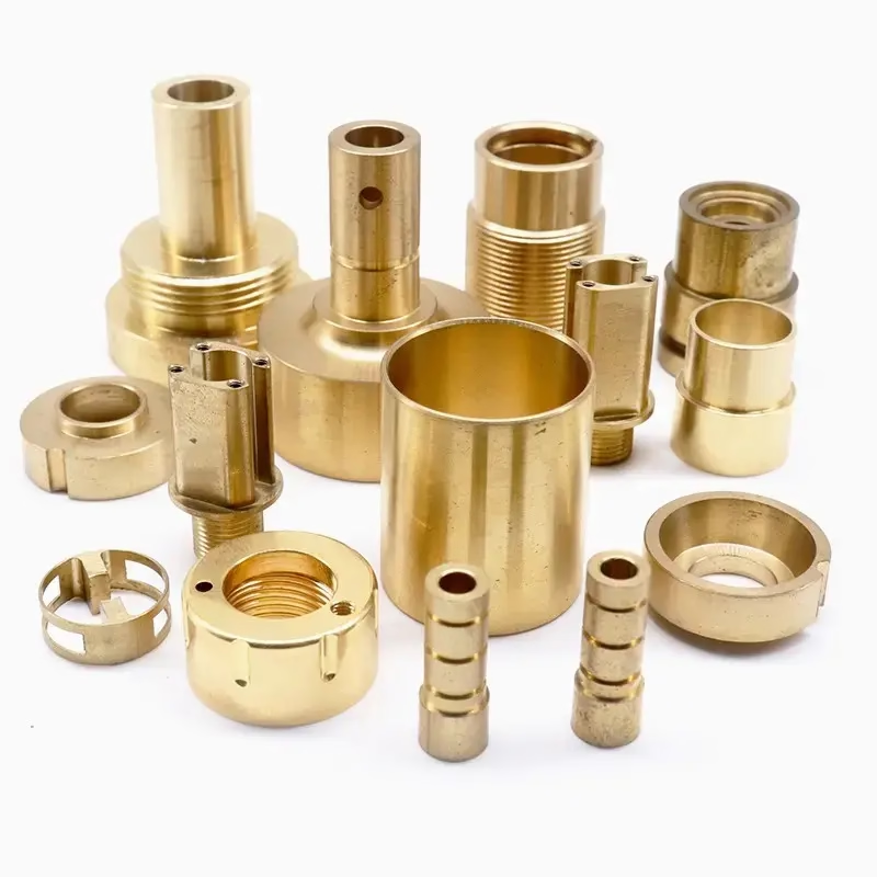
Plastics turn well with sharp, polished tools and high spindle speed. PEEK and carbon fibre are abrasive, so tool wear matters more than cutting force. Copper and brass families such as C36000 cut freely, but beryllium copper needs attention to dust control.
Magnesium AZ31B and AZ91D cut easily but require chip handling discipline. We treat the swarf as a controlled material, not as ordinary scrap.
Fixturing, Run Size, and Why Part Count Changes the Method
For bar work, a bar feeder or collet chuck holds the blank and the machine runs unattended. This is the cheapest way to make turned parts, and it works from a single prototype up to 10,000+ part runs. We have no minimum order quantity.
For chucked work, the blank is a casting, forging or saw-cut billet. The first operation grabs the outside diameter, the second op flips the part and machines the back. Two ops mean two fixtures and a positional relationship between them. If the drawing controls concentricity between front and back features, that relationship has to be built into the fixtures, not assumed.
Run size changes the answer. One prototype justifies soft jaws and a quick program. A 10,000-part run justifies a dedicated fixture, a custom form tool, and sometimes a second spindle so the back side is finished in the same cycle.
Tolerances and volumes interact in a way that surprises people. A ±0.005 mm callout on 50 parts is a normal turning job. The same callout on 50,000 parts is a process control project, because tool wear over the run has to be predicted, not just measured.
This is why we ask about annual volume and not just the immediate order. It changes how we plan the setup.
Turning vs Milling: Choosing the Process by Feature
Read the feature first, then the process.
| Feature on the drawing | Turning is right when | Milling is right when |
|---|---|---|
| Round shaft or bushing | Single centerline, diameters along one axis | Part is a plate or has no axis of rotation |
| Cross hole or face slot | Live tooling or mill-turn available | Feature is deep or needs a flat floor |
| Thread | External or internal on a turned diameter | Thread is on a face or an odd angle |
| Pocket or cavity | Pocket is on the end face and shallow | Pocket is deep with square internal corners |
| Thin wall tube | Wall 0.5 mm or more with soft jaws | Wall is under 0.5 mm or the profile is non-round |
| Tolerance ±0.005 mm | Feature is a diameter or a face | Feature is a hole position across a plate |
| Prototype, one piece | Bar stock, quick program, no fixture | Part starts as plate or needs 5-sided access |
| 10,000+ parts | Bar feeder, second spindle, form tools | Complex 3D surfaces need simultaneous 5-axis |
When Turning Is the Wrong Answer
If the part is round along one centerline and the tight tolerances sit on diameters or faces, turn it. If the critical features run across the axis, sit on a flat plate, or need square internal corners, mill it or send it to a mill-turn center instead of forcing it onto a lathe.
Questions Engineers Ask About Turned Parts
What is the smallest diameter you can turn?
We regularly turn parts down to Ø0.5 mm on small precision work, and bar-fed work typically starts around Ø3 mm. Below that, the limiting factor is usually bar straightness and tool deflection, not the machine.
If your part is smaller than that, send the drawing and we will tell you whether turning, Swiss-style work, or another process is the honest answer.
Can you turn a part and mill cross features in one setup?
Yes, on our mill-turn centers. A cross hole, face slot, or hex can be cut while the part is still in the same grip, which removes a second fixture and the positional error that comes with it.
If the cross feature is deep or has a square internal corner, we may still move it to a 5-axis mill. The setup that gives the best result depends on the geometry, not on the machine list.
How do you handle parts that need a tight concentricity between two ends?
Concentricity between front and back features is a fixturing problem before it is a machining problem. We either finish both ends in one setup on a mill-turn center, or we build the second-op fixture so the datum is transferred from the machined surface, not from the saw-cut blank.
This is one of the first things we look at during the free DFM review, because it is much cheaper to fix on the drawing than in the fixture.
What surface finish can turning achieve without grinding?
On a stable setup with the right insert, turning reaches Ra 0.2–0.8 μm on aluminum, brass and free-machining stainless. Ra 0.8–1.6 μm is routine for most turned steel parts.
If you need better than Ra 0.2 μm, that is a grinding or lapping operation. We will say so rather than quote a turning process that cannot deliver it.
Do you work from Savannah drawings and CAD files directly?
Yes. We work from STEP, IGES, X_T, DWG, DXF and PDF drawings. Uploads are treated as confidential, and an NDA is available on request before you send anything.
Quotation and a free DFM analysis come back within 12 hours, and production can start within 24 hours of approval. Parts normally ship in 3–5 days.
What certifications cover turned parts?
Our quality system holds ISO 9001:2015, IATF 16949:2016, ISO 13485:2016 and ISO 27001:2022. That covers general industrial work, automotive, medical devices and information security.
Inspection is 100% before shipment, with raw material check, in-process monitoring and final inspection. Dimensional reports are provided on request.
Send the Drawing, Get a Turning Answer in 12 Hours
Upload your turned part and we will return a quotation plus a free DFM analysis within 12 hours, with no minimum order quantity.
12-hour quote100% inspectionNo MOQ
More from the shop floor
We publish setup notes, tooling trials and inspection data from the factory floor.











