
CNC Turning Parts: Basic Guide for Engineers
Turning removes material from a rotating workpiece with a single-point tool. This CNC turning parts basic guide explains the cutting mechanics, the feature types that belong on a lathe, and the geometry that should be milled instead. Read it before you release a drawing.
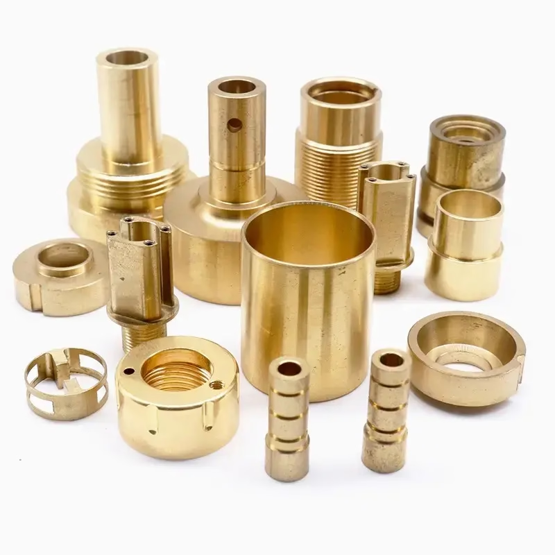
How a Lathe Actually Cuts
On a lathe the workpiece spins and the tool stays close to stationary. A bar of 6061 or 303 stainless is clamped in a chuck or collet, the spindle brings it up to surface speed, and a single-point insert travels along the Z axis (longitudinal turning) or across X (facing). The insert shears off a continuous chip at a set feed per revolution, usually 0.05–0.3 mm/rev for roughing and 0.03–0.1 mm/rev for finishing.
That number matters more than spindle rpm. Feed per revolution sets the theoretical cusp height left on the surface. At 0.05 mm/rev with a 0.8 mm tool nose radius, the theoretical Ra lands near 0.3 μm. Push the feed to 0.2 mm/rev and the same insert leaves roughly 2 μm. So surface finish on a turned part is mostly a feed decision, not a polishing decision.
Depth of cut controls how much material comes off per pass. Roughing passes often run 1–3 mm radially on aluminum and 0.5–1.5 mm on stainless. Finishing passes take 0.1–0.4 mm so the tool does not deflect. On a slender shaft the tool will push the part away from itself, so the cut gets shallower and the diameter drifts. That is why long, thin turned parts need support, not more spindle speed.
Turning is a continuous-cut process, so heat leaves with the chip. That is a real advantage over milling, where the tool enters and exits the cut thousands of times per minute. In 303 stainless or C36000 brass, the chip breaks cleanly and the tool life is long. In gummy materials like pure copper or soft aluminum, the chip can smear, and a sharper insert geometry or a higher rake angle is the fix.
- 1Feed sets finish0.03–0.1 mm/rev finishing, 0.05–0.3 mm/rev roughing.
- 2Speed sets tool lifeSurface speed in m/min, not rpm, is what the insert sees.
- 3Depth sets deflectionLarger radial engagement pushes slender parts away from the tool.
Features That Belong on a Lathe
Anything with rotational symmetry is a turning candidate. Shafts, pins, bushings, spacers, threaded studs, hydraulic fittings, valve bodies, and flanges all start life as a bar or a forging between centers. If the part's primary datum is an axis, the lathe should cut it first, because turning produces that axis with one continuous motion and no tool-change error.
Threads are a natural fit. A single-point tool or a die head cuts external threads in one helical pass. Metric M3 through M30 and unified 4-40 through 1-8 are routine. Internal threads need a boring bar small enough to enter the hole; below about M4 the bar gets fragile and thread milling on a mill-turn center is often the better route.
Grooves, reliefs, and undercuts are common on turned parts because they are just a plunge with a narrow insert. O-ring grooves, retaining-ring grooves, and thread reliefs all fall into this group. Keep the groove width at least 0.5 mm wider than the smallest available insert, or the shop will have to interpolate it, which costs cycle time.
Cross-drilled holes, flats, and slots are not turning features in the strict sense, but they are routinely done on the same machine. A mill-turn center with live tooling can drill a radial hole or mill a hex flat without a second setup. When you see a turned part with four bolt holes on a flange, that is mill-turn work, not pure turning.
- 1Axis as datumIf the drawing's primary datum is a centerline, turn it first.
- 2ThreadsM3–M30 and 4-40 to 1-8 are standard single-point work.
- 3Mill-turn crossoverRadial holes and hex flats need live tooling, not a plain lathe.
2-Axis, 4-Axis and 5-Axis Turning
A 2-axis lathe moves the turret in X and Z only. It is the fastest and cheapest way to make a simple round part, and for a straight shaft with a few diameters it is almost always the right machine. Cycle times are short because there is no rotary axis to position and no extra setup to plan.
A 4-axis lathe adds a second turret or a Y axis, so two tools can cut at once or a tool can move off-center. That off-center motion lets the same setup drill a radial hole or mill a small flat. For a fitting with a cross port, this removes a second operation and the re-fixturing error that comes with it.
A 5-axis mill-turn center adds full rotary motion of the tool or the workpiece. On a Ø400 mm rotary table, a single setup can reach features on five faces of a valve body. We run 16 simultaneous 5-axis machining centers, and the payoff is positional accuracy that does not depend on how well a second setup was indicated in.
The trade-off is programming and cycle time. A 5-axis toolpath is slower to prove out and usually runs longer than the same part split across a lathe and a mill. Use 5-axis when the feature count or the tolerance stack makes a second setup risky, not just because the machine is available.
- 12-axisFastest for shafts and simple diameters.
- 24-axisAdds Y or a second turret for off-center work.
- 35-axis mill-turnOne setup for multi-face parts; longer cycle, tighter stack.
Tolerance, Finish and Size Limits
Our standard turning tolerance is ±0.005 mm (±0.0002 in) on diameters up to 4,000 mm in length. That number is achievable on a rigid setup with a sharp insert and a controlled temperature, but it is not automatic. On a long shaft the diameter will move as the part heats and as the tool wears, so the drawing should state which diameters actually need the tight band.
Surface finish is quoted in Ra. As-machined turning lands at Ra 1.6–3.2 μm. A finishing pass with a wiper insert reaches Ra 0.8–1.6 μm. For Ra 0.2–0.8 μm you need a slower feed, a larger nose radius, or a secondary operation such as polishing or tumbling. Specify the finish only where it functions, because every step down adds cost.
Size limits are set by the machine envelope, not by the material. Our largest turning travel is 4,000 × 400 × 150 mm, with medium and compact envelopes at 750 × 1,150 × 550 mm and 500 × 500 × 450 mm. A part that fits the envelope may still be impractical if its length-to-diameter ratio is above about 8:1 without a steady rest.
Material choice drives the rest. Aluminum 6061-T6 and 7075 turn cleanly at high speed. Stainless 303 and 316L need lower surface speed and more coolant. Titanium TC4 (Ti-6Al-4V) and Inconel cut at a fraction of the aluminum speed and will work-harden if the tool rubs instead of cuts. Plastics like POM and PEEK turn well but need sharp tooling and light feeds to avoid melting.
- 1Blanket tolerance is a trapTighten only the diameters that mate with something.
- 2Finish stepsRa 3.2 as-machined, 1.6 with a wiper, 0.8 with polishing.
- 3Slender partsAbove 8:1 length-to-diameter, plan for a steady rest.
When Turning Is the Wrong Process
If the part is a flat plate with a pocket, turning cannot make it. There is no rotational symmetry, so the material has to be milled or the design changed to a turned hub with a separate plate. Forcing a plate onto a lathe means a face-drive setup and a long cycle, and the cost will show it.
Square and rectangular stock with features on all four sides belongs on a mill. A lathe can face it and drill it, but the geometry that defines the part is in the corners, and those need a rotating tool. The same applies to thin walls: a 0.5 mm wall on a 50 mm diameter tube will chatter and distort under chuck pressure, no matter how light the finishing pass.
Very small holes create a different problem. Below Ø0.5 mm, a drill is fragile and the chip is hard to clear. A turned part can still carry the hole, but it may need to be drilled on a mill-turn center or finished by EDM. The turning operation is fine; the drilling is the constraint.
Prototype quantities are the one case where turning is almost always worth it. There is no minimum order quantity here, so a single turned part and a 10,000-part run use the same setup logic. If the design later moves to casting or molding, the turned parts validate the geometry before tooling is cut.
- 1No symmetry, no turningFlat plates and boxes belong on a mill.
- 2Thin wallsChuck pressure distorts anything under about 1 mm.
- 3Tiny holesBelow Ø0.5 mm, expect mill-turn or EDM.
Turning vs Milling: Which Process Fits
Match the feature to the machine before you release the drawing.
| Feature | Turning | Milling |
|---|---|---|
| Cylindrical shaft | First choice, one setup | Impractical, no axis |
| Flange face + bolt circle | Face on lathe, holes on mill-turn | Bolt circle is natural |
| External thread | Single-point, fast | Thread mill, slower |
| Internal pocket | Not a turning feature | Standard operation |
| Hex flat on a stud | Live tooling | Simple with an indexer |
| Thin wall (<1 mm) | Chatter risk | Better clamping options |
| Small deep hole (<Ø0.5 mm) | Drill is fragile | Mill-turn or EDM |
| Prototype, 1 piece | No MOQ, fast setup | Same, if geometry fits |
The Short Version
If the part has a centerline and you need round features at tight tolerance, turn it. If the defining geometry is flat, square, or off-axis, mill it. A mill-turn center covers the middle, but it costs more cycle time than either process alone.
Turning Questions Engineers Ask
Can a turned part hold ±0.005 mm on every diameter?
Not realistically. The tight band is achievable on a rigid, short part with a sharp insert, but a long shaft moves as heat builds and the tool wears. Mark the diameters that mate with a bearing or a bore and leave the rest at a general tolerance. That keeps the cycle time and the inspection cost where they belong.
How do I decide between a 2-axis lathe and a mill-turn center?
Count the features that are not parallel to the centerline. If there are none, a 2-axis lathe is faster and cheaper. If there is one radial hole or one hex flat, a 4-axis lathe with live tooling usually wins. Above three or four off-axis features, a 5-axis mill-turn center removes the second setup and the stack-up that comes with it.
What surface finish can turning reach without a secondary operation?
As-machined turning gives Ra 1.6–3.2 μm. A finishing pass with a wiper insert gets to Ra 0.8–1.6 μm. Below that, you are looking at polishing, tumbling, or a slower finishing pass with a large nose radius. Specify Ra 0.2–0.8 μm only on sealing surfaces and bearing journals, because every step adds cost across the whole batch.
Does material choice change the turning setup?
Yes. Aluminum 6061-T6 and 7075 run at high surface speed with light coolant. Stainless 303 and 316L need lower speed and flood coolant to control heat. Titanium TC4 and Inconel cut much slower and will work-harden if the insert rubs. Plastics like POM and PEEK need sharp tooling and light feeds, or the chip melts and welds to the cut.
What length-to-diameter ratio needs a steady rest?
Above about 8:1, the part starts to deflect away from the tool and the diameter drifts. A steady rest or a tailstock supports the free end and brings the ratio back into a workable range. If the design allows, splitting a long slender part into two shorter pieces with a joint is often cheaper than the extra support setup.
Is there a minimum order quantity for turned parts?
No. We run from one prototype to 10,000+ part runs on the same setup logic. A single turned part is a useful way to validate a geometry before committing to a casting or molding tool. Uploads are secure and confidential, and an NDA is available on request.
Send Us Your Turned Part Drawing
Upload a STEP file and get a quotation with a free DFM analysis within 12 hours. Production can start within 24 hours, and every part is inspected before it ships.
12-hour quote100% inspectionNo MOQ
More From the Shop Floor
We publish setup notes, tooling trials and inspection data from the factory floor.











