
CNC Sheet Metal Machines: How Flat Stock Becomes a Finished Part
A working explanation of the machines behind sheet metal fabrication: what each one does to the sheet, what tolerance it can hold, and where it stops being the right choice. Written for design engineers and buyers who need to pick a process, not a brochure.
What CNC Sheet Metal Machines Actually Do
CNC sheet metal machines take flat stock and change its geometry without removing much material. A controller reads a program and drives the tool along a path or to a stop position. The sheet stays a sheet. What changes is the outline, the holes, and the bends.
That is the key difference from CNC milling. A mill starts with a block and cuts a shape out of it. Sheet metal work starts with a 0.5 mm to 6 mm sheet and folds a shape out of it. Material cost is lower, weight is lower, and the part is usually a housing, bracket, panel or chassis rather than a load-bearing solid.
The machine set is small and each unit has one job. Cutting machines separate the part from the nest. Punch presses cut holes and notches. Press brakes form bends. Tapping and deburring stations finish the edges. One part may touch three or four of them in a single day.
Because the program is digital, the same file that runs the laser can drive the brake. That shared geometry is why sheet metal prototyping and production stay close together. Change a hole in the CAD model and the nest, the punch path and the bend program all update from one source.
How Cutting Machines Separate Part From Nest
Fiber laser cutting is the default for thin sheet. A focused beam melts and vaporizes metal along a programmed path, assisted by nitrogen or oxygen. For 1 mm mild steel, a typical cut runs at 20 to 40 m/min with nitrogen assist. Thicker stock slows down fast: 6 mm mild steel may run at 2 to 3 m/min.
The heat-affected zone matters more than most drawings admit. On 1 mm stainless, the HAZ is roughly 0.1 to 0.2 mm wide. It is usually invisible after finishing, but on a part that will be bent sharply near a cut edge, that slightly harder zone can crack. Keep bend lines at least 2× material thickness away from a laser-cut edge.
Plasma cutting takes over above roughly 12 mm where laser cost per part climbs. It cuts faster on thick plate but leaves a rougher edge, often 0.2 to 0.5 mm of dross that needs grinding. Waterjet cuts any thickness with no heat at all, which suits titanium and thick aluminum, but it is slow and the abrasive garnet adds cost.
Punch presses are the fourth option and the fastest for repetitive work. A turret punch can hit 200 to 300 strokes per minute and combine punching, notching and forming in one setup. The trade-off is tooling: every hole shape needs a matching punch and die, so punches win on volume and lose on one-off geometry.
Press Brakes, Bend Allowance and Springback
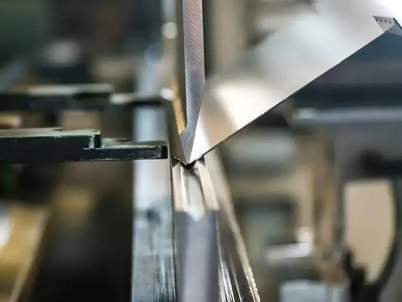
A press brake bends sheet by pressing it between a punch and a V-die. The inside radius is set by the die opening, not by the punch tip, in most air-bending setups. A common rule is that the inside radius equals roughly one-sixth of the V-die width. Choose a 12 mm die and you get about a 2 mm inside radius in mild steel.
Bend allowance is where most design errors start. When sheet bends, the outer fibers stretch and the inner fibers compress, so the flat length is not the sum of the leg lengths. The neutral axis sits at roughly 0.3 to 0.5 of thickness from the inside surface, depending on the material and the R/T ratio. CAM software calculates this, but the model has to carry the correct K-factor or the flat pattern will be short.
Springback is the second correction. Steel springs back 1° to 3° after the punch releases; aluminum 2° to 4°; 304 stainless can reach 5°. The brake compensates by over-bending, and the operator confirms with a test piece before running the batch. On a 90° flange in 2 mm 304, expect the controller to target about 93° to 95°.
Minimum flange length is a hard limit. If the flange is shorter than roughly 4× material thickness plus the die width, the punch cannot reach the bend line and the part will slip. A 2 mm sheet on a 12 mm die needs a flange of at least 20 mm. Designers who ignore this get parts that cannot be formed at all.
Where Sheet Metal Tolerances Break Down
Laser-cut profiles hold ±0.1 mm on thin sheet and ±0.2 mm on 6 mm plate. That is normal for the process and usually fine for a panel. Hole-to-hole position on the same flat part is tighter, often ±0.05 mm, because the machine moves in one continuous coordinate system.
Bends are the loose link. A formed angle typically holds ±0.5° to ±1°, and a flange height holds ±0.2 mm to ±0.5 mm depending on thickness and die condition. Stack three bends and the accumulated error on the last flange can reach ±1 mm. If a drawing calls for ±0.1 mm across a bent part, sheet metal is the wrong process.
That is the point where machining takes over. When a feature needs ±0.005 mm, or a bore needs Ra 0.8–1.6 μm, the part should be milled or turned rather than formed. Many real assemblies mix both: a formed enclosure with a machined insert, a bent bracket with a reamed hole.
Welding adds its own distortion. A 1 m long seam in 2 mm steel can pull 1 to 3 mm out of flat. Tack welds, a fixture, or a post-weld straightening pass keep it in check, but the drawing should carry a flatness callout if it matters.
Material Choice and What It Does to the Process
Mild steel and aluminum are the easiest to cut and bend. 5052 and 6061 aluminum bend well in the annealed and T6 conditions respectively, though 6061-T6 cracks if the bend radius is tight. Keep the inside radius at 1× to 2× thickness on 6061-T6, or specify 5052 instead.
304 and 316 stainless work-harden as they deform. Bend them with a larger radius and more springback compensation. 304 holds up outdoors; 316L is the pick for medical and marine parts. Both can be laser cut cleanly with nitrogen assist.
Finishing choices follow the material. Anodizing suits aluminum and gives a hard, non-conductive surface in clear, color or hardcoat form. Powder coating covers steel and aluminum with a thicker, more impact-resistant layer. Electroless nickel adds corrosion resistance and solderability without changing dimensions much.
Laser marking is often cheaper than a label. Minimum character height is 1.5 mm, so part numbers, QR codes and traceability marks can go straight onto the panel after finishing.
Choosing Between Sheet Metal Cutting Methods
Ranges are typical for the materials named; confirm against your actual drawing.
| Method | Best thickness | Edge quality | When it wins |
|---|---|---|---|
| Fiber laser | 0.5–6 mm steel, 0.5–4 mm aluminum | Clean, HAZ 0.1–0.2 mm | Thin sheet with many holes and tight nests |
| Plasma | 6–25 mm plate | Rough, 0.2–0.5 mm dross | Thick plate where speed beats finish |
| Waterjet | Any thickness | Smooth, no heat | Titanium, thick aluminum, heat-sensitive alloys |
| Turret punch | 0.5–4 mm sheet | Clean, slight burr | High volume with repeating hole patterns |
| Press brake | 0.5–6 mm sheet | Not applicable | Turning flat nests into 3D formed parts |
When to Form and When to Machine
If the part is a flat-derived enclosure, bracket or panel with bends at ±0.5° and holes at ±0.1 mm, form it from sheet. If any feature needs ±0.005 mm, a reamed bore or Ra 0.8–1.6 μm, machine that feature and form the rest.
Common Questions
Can a CNC sheet metal machine hold ±0.005 mm?
No, not on a formed or cut edge. Laser cutting holds about ±0.1 mm on thin sheet and bending loosens that further to ±0.5° or ±0.2 mm per flange.
The ±0.005 mm figure belongs to CNC milling and turning, which is why mixed assemblies often machine the tight features and form the rest.
What is the largest sheet you can process?
Our machining centers handle up to 4,000 mm maximum processing size, and large-format cutting tables take standard 2,500 × 1,250 mm and 3,000 × 1,500 mm sheets without splicing.
For very long parts, the limiting factor is usually the press brake bed rather than the cutting table.
Do I need tooling before production starts?
Laser and waterjet cutting need no hard tooling at all, so a single prototype can run from a DXF file. Turret punching does need a punch and die for each hole shape.
If your design uses standard round and square holes, that tooling is often already on the shelf.
How do you control bend accuracy across a batch?
We run a test piece from the first sheet, measure the angle and flange height, and adjust the controller before the batch continues. In-process checks repeat through the run, and every part is inspected before shipment.
Reports are available on request.
Which materials do you cut and form?
Aluminum 5052, 6061, 6061-T6, 2024, 5083, 6063, 6082 and 7075; stainless 303, 304, 316, 316L, 420, 430 and 17-4PH; steel 1018, 1045, 4130, 4140, A36 and tool steel; plus copper, brass, titanium and Inconel.
Tell us the alloy and temper and we will flag any bend radius or springback issue before quoting.
Can sheet metal parts be finished after forming?
Yes, and that is the usual order. Debris and burrs are removed first, then the part is anodized, powder coated, plated or bead blasted.
Laser marking goes last so the mark sits on the finished surface. Minimum character height is 1.5 mm.
Send Your Sheet Metal Design
Upload a DXF, STEP or PDF drawing and we will return a quotation with free DFM analysis within 12 hours.
12-hour quoteNo minimum order quantityNDA on request
GreatLight Elsewhere
We publish setup notes, tooling trials and inspection data from the factory floor.











