
Advantages of Sheet Metal CNC Machining
This page is for design engineers and sourcing engineers who need to know what sheet metal CNC work actually buys them. It covers cut and bend limits, tolerance stacking, material behavior, and the cases where a machined or cast part is the better call.
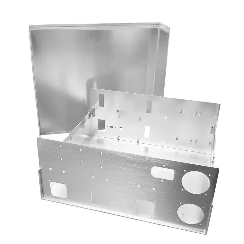
What sheet metal CNC machining actually means
It is not one process. It is a group of computer-controlled operations that share one workflow.
Where the process starts and stops
The workflow covers the computer-controlled operations applied to flat stock: laser or plasma cutting, punching, CNC bending, and secondary machining of holes, slots, countersinks and tapped features. Material arrives as sheet, usually 0.5 mm to 6 mm thick in our shop, and leaves as a formed part. Nothing is removed from a solid billet, so the cost curve follows the blank size and the number of operations, not the volume of chips.
Four operations do most of the work. Cutting defines the flat pattern. Bending sets the third dimension. Punching or machining adds holes and edge features. Finishing handles corrosion, appearance and electrical contact. Each step adds its own tolerance, and those tolerances stack along the part. A bracket that is dimensioned across three bends will not hold the same accuracy as a bracket dimensioned across one.
That distinction matters when you compare this route against milling from solid. Cutting and forming are fast because the tool never has to clear a pocket. The trade is that formed geometry is limited by bend radius, flange height and material ductility. If a feature sits inside a deep pocket or needs a true 3D contour, a machining center is the correct tool, not a press brake.
What the tolerances look like in practice
Published numbers are easy to misread. A cut edge on 2 mm aluminum can hold roughly ±0.1 mm, while a machined hole in the same part reaches ±0.005 mm (±0.0002 in). Both figures are real on the same drawing, and the gap between them is the point. Assign the tight tolerance only to the features that need it.
Bend angles typically sit within ±0.5° to ±1°, depending on material, thickness and bend length. The inside radius is set by the tooling and by the material, not by the CAD model. Springback pushes the finished angle back by a fraction of a degree, so the press brake operator compensates rather than chasing the nominal value.
Hole position relative to a bend is the usual source of argument. A hole placed closer than roughly two material thicknesses to the bend line will distort. Move it to three thicknesses and the problem largely disappears. Designers who respect that rule get parts that fit on the first build.
Surface finish follows a similar pattern. Cut and formed surfaces arrive near Ra 3.2 μm. Machined faces can be taken to Ra 0.8–1.6 μm, and finer on request. Cosmetic faces should be identified on the drawing instead of left to the shop to guess.
Feature tolerance and process choice
Typical values on 1–3 mm aluminum or mild steel. Confirm on your drawing before release.
| Feature | Typical tolerance | How it is produced |
|---|---|---|
| Cut profile | ±0.1 mm | Laser or punch |
| Bend angle | ±0.5° to ±1° | CNC press brake |
| Hole position | ±0.1 mm | Punch or laser |
| Machined hole | ±0.005 mm | CNC mill or drill |
| Countersink depth | ±0.05 mm | Secondary machining |
| Surface, machined | Ra 0.8–1.6 μm | Face mill or finish pass |
Material behavior drives the design
Aluminum 5052 bends well and resists corrosion, which makes it the default for enclosures. 6061 machines cleanly but cracks if the bend radius is pushed too tight. 7075 should be formed in a soft temper or not formed at all. For chassis work we often cut and bend in 5052, then machine the interface features in a separate 6061 block.
Stainless 304 work-hardens at the bend, so a generous radius and a slower press stroke are required. 316L behaves similarly and is preferred where corrosion resistance matters more than formability. Cold-rolled steel 1018 and 1045 form predictably and take powder coat or black oxide without extra prep.
Titanium and Inconel are rarely good candidates for a press brake. They are cut and then machined. Copper and brass form easily but scratch easily, so handling and packaging need attention. Plastics such as ABS, PC and POM can be cut and bent in thin sections, though heat-assisted bending is a different process with a different tolerance range.
Why the cost curve looks different
Setup dominates at low volume. A laser program, a bend program and a first-article check cost roughly the same whether you run ten parts or a thousand. That is why a prototype batch of five brackets is expensive per piece, and why the tenth batch of five hundred is not.
At higher volume, punching overtakes laser cutting. A progressive die or a turret punch removes the per-part laser time, and the cost per part drops sharply. The crossover depends on blank complexity and hole count, not on a fixed quantity. We quote both routes when the volume sits near the boundary.
Nesting matters more than most engineers expect. Part orientation on the sheet determines how much scrap you pay for. A small rotation that lets two blanks share an edge can cut material use noticeably. Sending a DXF rather than a PDF drawing lets us nest properly and quote the real number.
Secondary machining adds cost but saves assembly. A tapped hole, a counterbore or a milled flat on a formed bracket is cheaper than a separate machined insert plus fasteners. It also removes a stack-up error from the assembly.
When this is the wrong process
Deep pockets, internal channels and true 3D contours cannot be formed. If the part needs a curved surface in two directions, a 5-axis machining center is the answer. We run 16 simultaneous 5-axis centers for exactly that kind of geometry.
Very thick stock changes the economics. Above roughly 6 mm, bending forces rise, tooling wear accelerates and the advantage over a machined plate narrows. A 12 mm plate is usually a milling job.
Tight flatness across a large formed panel is hard to guarantee. Welding pulls, forming releases residual stress, and the part moves. If flatness is the critical callout, design in a machined face or a stiffening rib rather than fighting the process.
Cosmetic requirements also decide the route. A brushed, anodized front panel with visible grain is easier to control when it is machined flat and then finished, because the grain direction is set by the tool path rather than by the rolling direction of the sheet.
Questions engineers ask
Which sheet thicknesses can you form?
We work with 0.5 mm to 6 mm sheet as standard. Thinner stock is possible but handling and flatness become the limiting factors rather than the press brake.
Above 6 mm the bend force and tooling wear rise quickly, and a machined plate is usually the better route.
Can formed parts also carry machined features?
Yes. Holes, counterbores, tapped threads and milled flats are added after forming on our CNC mills. This is common on brackets and chassis where an interface face needs a tight tolerance.
Machined features reach ±0.005 mm while the formed geometry holds its own wider tolerance, so separate the two on the drawing.
How does bending affect hole position?
A hole placed within about two material thicknesses of the bend line will distort as the material stretches. Move it to three thicknesses and the distortion is normally acceptable.
If the hole must sit close to the bend, cut it undersize and machine it to final size after forming.
What finishes can be applied after forming?
Anodizing in clear, color, hardcoat and conductive types; electroless nickel, zinc, silver and gold plating; powder coating and black oxide; bead blasting, tumbling, brushing and polishing.
Laser marking and engraving are available with a minimum character height of 1.5 mm.
What is the smallest order you accept?
There is no minimum order quantity. We run from one prototype to 10,000+ part runs on the same equipment.
Quotation and a free DFM analysis come back within 12 hours, and production can start within 24 hours of approval.
How do you handle drawings and confidentiality?
Uploads are treated as secure and confidential. An NDA is available on request before you send files.
Send DXF or STEP rather than a flat PDF where possible, so nesting and feature checks are accurate.
Send a drawing and get a real number
Our engineers review your flat pattern and formed features, flag anything that will not hold tolerance, and return a quote with a free DFM analysis within 12 hours.
12-hour quote100% inspectionNo minimum order quantityNDA on request









