
CNC Machining Finish: What Actually Sets Surface Quality
A practical read on CNC machining finish for engineers and buyers who have to approve a drawing. We cover what creates the surface, how Ra numbers map to real parts, and where the limit sits. By the end you can tell whether a quoted finish is achievable or wishful.
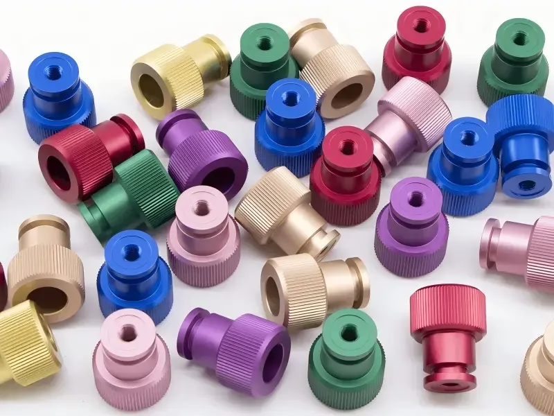
Where a CNC machining finish comes from
Every machined surface is a record of the tool path. A rotating cutter removes material in overlapping arcs, and what you see afterward is the sum of those arcs: feed marks, tool pressure marks, and whatever the material did after the cutter left. Change the feed rate and the spacing between marks changes. Change the nose radius and the height of each ridge changes. Two shops running the same program on the same material can still hand you different surfaces.
The dominant variable is feed per tooth, usually written fz. A two-flute end mill at 0.05 mm per tooth leaves a rougher surface than the same cutter at 0.02 mm per tooth, because each insert edge cuts a deeper scallop. This is why finishing passes are run light. Shops drop the feed, raise the spindle speed, and accept a longer cycle to buy a smoother wall.
Depth of cut matters too, but not in the way most people expect. A deep finishing pass deflects the tool and the workpiece, and that deflection shows up as chatter or a wavy wall rather than a clean scallop pattern. Light radial engagement keeps cutting forces low and the surface predictable.
The material decides how far you can push this. Aluminium 6061 and 7075 cut cleanly and hold a good finish across a wide window. Stainless 316 and 17-4PH work-harden at the cutting edge, so a dull tool or a dwell in the path leaves a torn, gummy surface that no polishing pass fully hides.
How to read Ra on a CNC machining finish callout
Ra is the arithmetic mean deviation of the profile from its center line, measured over a sampling length. It is an average, so it hides peaks. Two surfaces can share an Ra of 0.8 μm while one has a few deep scratches and the other is uniformly scalloped. If your part seals against an O-ring or slides against a mating face, the peaks matter more than the average, and you should specify Rz or Rmax as well.
The practical bands are narrow. As-machined surfaces from a normal finishing pass land around Ra 1.6–3.2 μm. A controlled finishing pass with a sharp tool and a light feed reaches Ra 0.8–1.6 μm. Below that you are into Ra 0.2–0.8 μm, which usually means a dedicated finishing operation, a smaller step-over, or a secondary process such as polishing.
Measurement method changes the number. A profilometer stylus with a 2 μm tip cannot resolve the bottom of a narrow groove, so it reports a smoother value than the surface really is. Optical systems read differently again. When a customer sends a finish requirement, we ask which instrument and which cutoff length produced the reference number. Without that, the target is guesswork.
Direction matters for function, not just appearance. A turned surface has circumferential lay. A milled surface has lay along the tool path. On a dynamic seal, lay running across the sealing direction can pump fluid; lay running along it usually seals better. The same Ra value can pass or fail depending on how the lay is oriented.
What each machining process can and cannot reach
Turning on a lathe produces the most consistent finish of the common operations, because the tool stays in contact continuously and the geometry is simple. A finish-turned 6061 shaft at Ra 0.8 μm is routine. Reaching Ra 0.4 μm on the same shaft needs a wiper insert or a slower feed, and the cycle time grows.
Milling is harder to control because the cutter enters and exits repeatedly. Corners and internal radii show the worst finish, since the tool slows, the chip load drops, and rubbing replaces cutting. A wall that measures Ra 1.0 μm in the middle can measure Ra 2.5 μm in a tight corner. If the drawing calls for a uniform finish, design generous corner radii and a cutter that can reach the bottom in one pass.
Small tools and deep cavities set a hard limit. A Ø3 mm end mill with a 30 mm reach flexes under load, and no feed adjustment removes that. We see drawings asking for Ra 0.4 μm on a 40 mm deep slot cut with a small tool. The honest answer is that it needs a different geometry, not a different program.
Hard materials shift the ceiling. Titanium TC4 and Inconel generate heat at the edge, and the surface work-hardens ahead of the cut. Finishes on these alloys are typically one band rougher than the same operation in aluminium. Magnesium cuts fast and finishes well but needs care with chips.
When the required finish is beyond what the cutter can produce, the part moves to a secondary operation: bead blasting to even out the look, tumbling for edge break, brushing for a directional grain, or polishing for a reflective surface. Each of these changes the surface, so inspect after the secondary step, not before.
When a tighter CNC machining finish is worth the cost
Tighter finish costs money in two ways: longer cycle time and more inspection. A finishing pass at half the feed adds minutes per part. If the surface is cosmetic only and sits on the outside of an enclosure, that money buys nothing the customer will notice. If the surface is a bearing bore, a hydraulic sealing face, or an optical mount, it buys function.
Ask what the surface has to do. Sealing faces need controlled peaks, not the lowest possible average. Sliding contacts need a finish that holds an oil film, which is often rougher than a polished surface, not smoother. Painted parts need an anchor profile, and bead blasting to Ra 2.0–3.0 μm gives paint something to grip. A mirror finish under paint is wasted work.
There is a floor below which more polishing stops helping. Once a surface reaches Ra 0.2 μm, further work mostly removes material and risks rounding edges that need to stay sharp. We have seen cosmetic panels polished past the point where the geometry still matched the drawing.
The sensible approach is to specify finish only where it carries a function, and mark the rest as-machined. That single decision usually removes a finishing operation from the quote and shortens lead time without touching part performance.
CNC machining finish bands and what produces them
Values assume sound tooling and a rigid setup; hard alloys land one band rougher.
| Finish band | Typical process | Good for | Watch out for |
|---|---|---|---|
| Ra 3.2 μm and up | Roughing or single-pass milling | Weld prep, hidden faces | Tool marks show through thin coatings |
| Ra 1.6–3.2 μm | Standard finishing pass | General machined parts | Corner finish is worse than walls |
| Ra 0.8–1.6 μm | Light feed, sharp tool, rigid setup | Bearing seats, mating faces | Needs clean chips and coolant flow |
| Ra 0.2–0.8 μm | Wiper insert or fine finishing pass | Sealing faces, sliding contacts | Cycle time climbs fast |
| Below Ra 0.2 μm | Polishing or lapping after machining | Optics, cosmetic panels | Edges round; geometry drifts |
The trade-off in one line
Specify a tight finish only where the surface has a job to do. Cosmetic panels and hidden faces should stay as-machined; sealing faces, bearing bores and sliding contacts earn the extra pass. If the drawing asks for Ra 0.4 μm on a deep pocket cut with a small tool, change the geometry before you change the program.
Common questions about CNC machining finish
Can you hit Ra 0.8 μm on a milled pocket?
Yes, on a rigid setup with a sharp cutter and a light finishing pass. The catch is the corners. A small internal radius forces the tool to slow and the chip load drops, so the corner reads rougher than the wall.
If the drawing requires uniform finish across the whole pocket, open the corner radii and give the cutter room to stay in cut.
Does anodizing change the finish number?
It changes the surface. Anodizing grows a conversion layer that follows the existing profile, so it tends to preserve and slightly amplify tool marks rather than hide them. A rough machined surface still looks rough after clear anodizing.
If the part is going to be anodized and looks matter, machine it one band smoother than the final target, or bead blast first for an even matte look.
Why does my part measure different from the reference sample?
Different instrument, different cutoff length, or a different measurement direction. A stylus profilometer and an optical system will not return the same number on the same surface.
Send the reference part alongside the drawing, or state the instrument and cutoff. Then both sides measure the same thing.
Is a smoother surface always better for wear?
No. Sliding and rotating contacts need some texture to hold lubricant. A mirror-polished bore can starve and score faster than a controlled Ra 0.8 μm bore.
Match the finish to the lubrication regime, not to the lowest number you can reach.
How do you verify finish on a production run?
We check the surface at the machine after the finishing pass, then confirm again during final inspection before shipment. Reports are available on request.
For cosmetic parts, we compare against an approved sample under the same lighting the customer uses.
Send us the drawing and the finish callout
We review every finish requirement against the geometry before quoting, so the number you get back is one the shop can actually hold.
12-hour quote100% inspectionNo minimum order quantity
More from the shop floor
We publish setup notes, tooling trials and inspection data from the factory floor.











