
Precision Manufacturing: How the CNC Machining Center Sets the Limit
Precision manufacturing is not a slogan. It is the sum of machine rigidity, axis count, thermal behavior and inspection. This page explains how a CNC machining center turns a drawing into a held tolerance, and where that tolerance stops being practical. Written for engineers and buyers who must judge a process before they commit a part to it.
In this article
- 1
- 2
- 3
- 4
- 5
- 6
- 7
How a machining center turns a drawing into a held tolerance
Precision manufacturing starts with a solid block of metal and a program. The controller reads G-code, drives the spindle and table along numbered axes, and swaps tools from a magazine. A modern machining center performs milling, drilling, boring and tapping without an operator touching the part between operations. That single setup is the real source of accuracy.
Machining center accuracy comes from stiffness, not speed. A cast-iron or polymer-concrete bed absorbs cutting force. Linear guides and preloaded ballscrews remove lost motion. The spindle holds a tool in a taper or HSK interface, and every micron of runout in that interface shows up in the wall of your part. When the machine is rigid, the cutter shears metal cleanly and the tool life is long.
The controller closes the loop. Glass scales or rotary encoders feed position back to the drive thousands of times per second. Thermal growth in the ballscrew is compensated in software. This is why a machining center can hold ±0.005 mm (±0.0002 in) on a good day and cannot hold it on a bad one. Temperature, chip load and tool wear all move the number.
The last step is inspection. A tolerance is only real if someone measures it. We check raw material, monitor in process, and inspect 100% of parts before shipment, with reports on request. That chain is what separates precision manufacturing from a machine that merely cuts fast.
- 1Rigidity firstA stiff frame beats a fast spindle for tight walls and thin floors.
- 2Single setupFewer setups mean fewer stacked datum errors.
- 3Closed loopFeedback scales cancel most of the screw's thermal drift.
- 4Measured, not assumed100% inspection before shipment; reports on request.
3-axis, 4-axis and 5-axis: what each one buys you
A 3-axis machining center moves X, Y and Z. The tool always points straight down. This is the cheapest, stiffest and fastest configuration, and it covers most prismatic parts: plates, housings, brackets, manifolds. If every feature can be reached from one direction, three axes are enough. Do not pay for more.
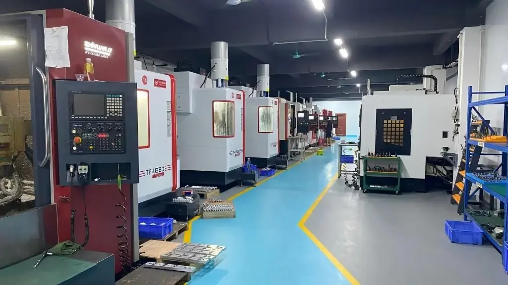
A 4-axis machine adds a rotary table, usually about a horizontal or vertical axis. The part indexes to a new face and the cut continues. This removes a second and third setup, which matters when hole patterns on four sides must line up. In our shop, 12 four-axis mills handle this class of work, with a typical rotary table around Ø400 mm.
A 5-axis machining center adds a second rotary axis so the tool can tilt. Two things change. First, you can reach undercuts and organic surfaces in one setup. Second, a short, rigid tool can be tilted to cut a deep pocket that would otherwise need a long, chattering end mill. We run 16 simultaneous 5-axis centers for exactly these cases.
Five axes are not free. They add cost, programming time and a new failure mode: the rotary table must be aligned and its center point verified. For a flat plate with a few holes, 5-axis is slower and no more accurate. Match the axis count to the geometry, not to the spec sheet.
- 13-axisPrismatic parts, one visible direction, lowest cost per part.
- 24-axisMulti-face features that must stay in one datum.
- 35-axisUndercuts, contoured surfaces, deep pockets with short tools.
- 4Not a quality badgeMore axes do not mean a tighter tolerance on a simple plate.
Where the accuracy stops, and why
The tolerance on a drawing is a negotiation with physics. We quote ±0.005 mm on a machining center, and that is achievable on a well-supported feature in stable conditions. It is a statement about the machine, not about every feature on every part. A deep bore 8× diameter deep with a long boring bar will not hold it. Neither will a thin wall that springs back after the cutter passes.
Thermal drift is the quiet error. The spindle grows as it heats, and a machine that ran all night is not the same shape at 2 pm. Controllers compensate, but they cannot compensate for a shop door left open in winter. For tight work, we let the machine warm up, keep coolant at a steady temperature, and schedule the critical cuts after the thermal curve flattens.
Surface finish is a separate axis of the problem. As-machined surfaces land around Ra 1.6–3.2 μm. A high-quality cut reaches Ra 0.8–1.6 μm. Fine finishing with a small stepover and a sharp cutter can reach Ra 0.2–0.8 μm, but it costs time. If your drawing calls for a mirror finish, ask whether the function needs it or whether the appearance does.
Material moves. Aluminium 6061 and 7075 cut cleanly and hold tight tolerances. Stainless 316L work-hardens if the feed is too light, so we take a heavier chip. Inconel and titanium TC4 (Ti-6Al-4V) generate heat at the edge, so tool life, not machine accuracy, becomes the limiting factor. The machine is the same. The process around it changes.
- 1Feature supportA short, rigid setup holds ±0.005 mm; a long boring bar does not.
- 2Thermal stateWarm-up and steady coolant matter more than the spec sheet.
- 3Finish is timeRa 0.2–0.8 μm needs small stepovers and sharp tools.
- 4Material sets the limitInconel and Ti-6Al-4V wear tools before the machine drifts.
What precision manufacturing actually looks like in each industry
In aerospace, the parts are few and the paperwork is heavy. A bracket or a housing must be traceable, and the tolerance must survive inspection. A 5-axis machining center cuts these in one setup so the datum stack stays short. We also hold ISO 9001:2015 and produce to drawing, with material certificates available.
Automotive and EV work runs the other way: higher volume, tighter cost, and IATF 16949:2016 as the baseline. Battery housings, motor mounts and sensor bodies are usually 3-axis or 4-axis jobs where cycle time decides the price. Fixtures are built for quick loading, and the same program runs for thousands of parts.
Medical devices bring ISO 13485:2016 and a different risk profile. Implant tooling, instrument handles and fluidic manifolds need clean edges and documented inspection. Surface finish often matters more than a tight dimensional callout, because a rough surface traps residue. We finish these with bead blasting, tumbling or polishing.
Robotics, electronics and industrial machinery sit in between. A robot arm joint needs concentric bores and a flat mounting face. An electronics chassis needs flatness and a clean anodized surface. Both are ordinary machining center work, and both fail if the setup is sloppy. The machine does not care about the industry. The process does.
- 1AerospaceLow volume, full traceability, 5-axis single-setup cuts.
- 2Automotive and EVIATF 16949:2016, cycle time driven, quick-load fixtures.
- 3MedicalISO 13485:2016, documented inspection, clean surfaces.
- 4Robotics and machineryConcentric bores, flat faces, anodized finishes.
When a machining center is the wrong process
A machining center removes material. If your part is a thin shell with a complex internal cavity, no cutter can reach inside it. That part belongs to 3D printing, vacuum casting or die casting, not to milling. We run those processes too, so we will say so rather than quote a job we cannot cut.
Wall thickness is the second boundary. Below roughly 0.5 mm, cutting forces deflect the wall and the tolerance opens up. You can still make the part, but plan for a finishing pass with light radial engagement and accept a looser number. If the wall must be 0.3 mm and held tight, the design, not the machine, needs to change.
Hardness matters as well. A machining center cuts hardened tool steel, but above roughly 45 HRC the tool life drops and the cost climbs. If the part is already heat treated, ask whether the critical features can be ground or EDM instead. Sometimes the answer is to machine soft, then harden, then finish only the tight surfaces.
Finally, consider volume. For 100,000 identical small parts, a machining center is slow and expensive per piece. Die casting or injection molding wins. A machining center is at its best from one prototype to 10,000+ part runs, where geometry is complex and the design is still moving. There is no minimum order quantity here.
- 1Closed cavitiesNo line of sight means no cutter; use 3D printing or casting.
- 2Walls under 0.5 mmDeflection opens the tolerance; plan a light finishing pass.
- 3Above 45 HRCTool life collapses; consider grinding or EDM for tight features.
- 4Very high volumeDie casting or molding beats milling on cost per piece.
From file to finished part, step by step
- 1Review the drawingWe check tolerances, datums and finishes, and send free DFM feedback within 12 hours.
- 2Choose the machine classLowest axis count that reaches every feature in one setup, from 3-axis up to 5-axis.
- 3Set the stock and datumsPick a blank with enough material for clamping, then define datums the machine can actually touch.
- 4Program and simulateVerify toolpaths, check for gouges, and confirm the tool reaches depth without shank rub.
- 5Cut the first articleRun one part, measure it, and adjust offsets before releasing the batch.
- 6Inspect and ship100% inspection before shipment, reports on request, parts ship in 3–5 days.
Which machine class fits which part
Pick the lowest axis count that reaches every feature in one setup.
| Machine class | Typical travel | Best-fit geometry | When it is the wrong choice |
|---|---|---|---|
| 3-axis | 500 × 500 × 450 mm | Plates, brackets, housings, manifolds | Features hidden on the back or sides |
| 4-axis | 500 × 310 × 200 mm | Shafts, hole patterns on four faces | Free-form contoured surfaces |
| 5-axis | 600 × 600 × 600 mm | Undercuts, impellers, organic shapes | Flat parts with simple through holes |
| Large 5-axis | 4,000 × 400 × 150 mm | Long frames, rails, structural beams | Small parts that fit a compact machine |
| Mill-turn | Ø400 mm rotary table | Parts needing turning and milling | Pure round work with no milled features |
The short answer
If your part is prismatic and reachable from one direction, use a 3-axis machining center. If it has undercuts, contoured surfaces or deep pockets that need a short tool, pay for 5-axis. If it is a closed hollow shell, do not machine it at all.
Questions engineers ask before releasing a part
How tight a tolerance can a machining center hold?
We quote ±0.005 mm (±0.0002 in) on a well-supported feature in stable shop conditions. That is a machine capability, not a promise for every feature.
A long boring bar, a thin wall or a deep pocket will open that number. Send the drawing and we will tell you which callouts are realistic.
Do I need 5-axis, or is 3-axis enough?
Count the directions from which a cutter must reach the part. If one direction covers every feature, 3-axis is cheaper, stiffer and faster.
Choose 5-axis when you have undercuts, free-form surfaces or deep pockets where a long tool would chatter. The extra cost buys setup reduction and tool rigidity, not a tighter tolerance by itself.
What surface finish should I put on the drawing?
As-machined runs about Ra 1.6–3.2 μm, a good cut reaches Ra 0.8–1.6 μm, and fine finishing reaches Ra 0.2–0.8 μm.
Every step finer costs cycle time. Specify the coarsest finish that satisfies the function, and reserve the fine number for sealing faces or sliding surfaces.
Which materials do you machine most often?
Aluminium 6061, 6061-T6, 2024, 5052, 6082 and 7075; stainless 303, 304, 316L, 17-4PH (SUS630); steel 1018, 1045, 4130, 4140 and 4340.
We also cut titanium TA1, TA2 and TC4 (Ti-6Al-4V), Inconel, magnesium AZ31B and engineering plastics such as POM, PEEK and PC.
How fast can you quote and ship?
Quotation and free DFM analysis come back within 12 hours. Production can start within 24 hours, and parts ship in 3–5 days.
There is no minimum order quantity, so a single prototype and a 10,000+ part run go through the same queue. Uploads are secure and confidential, and an NDA is available on request.
What if my design is not machinable?
We say so. Closed internal cavities, walls under 0.5 mm and features needing a tool that cannot reach are the usual problems.
Because we also run 3D printing, vacuum casting and die casting, we can route the part to the process that fits instead of forcing it onto a machining center.
Send the drawing, get a machining answer
Upload your files and an engineer will review the geometry, pick the machine class, and return a quote with DFM notes within 12 hours.
12-hour quote100% inspectionNo minimum order quantityNDA on request
More from the shop floor
We publish setup notes, tooling trials and inspection data from the factory floor.











