
CNC Machining Casting: How the Two Processes Fit Together
Casting gives you the near-net shape; CNC machining gives you the critical faces. This page explains where the boundary sits, what tolerance and finish each step can hold, and which parts should not use this route. Written for design and manufacturing engineers who have to pick a process before the drawing is frozen.
In this article
- 1
- 2
- 3
- 4
- 5
- 6
- 7
Key takeaways
Why cnc machining casting works as a combined route
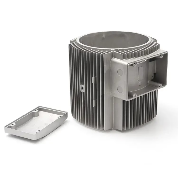
Die casting and CNC machining solve two different problems. The mold fills a cavity and reproduces a complex shape in one shot, including ribs, bosses, cooling channels and draft. The machining center then removes a thin layer from selected faces to create a flat, round or threaded feature that the mold could never hold to tolerance. Neither process does the other's job well, which is exactly why they are paired.
The economics come from moving metal only where the function demands it. A part that would need 40 minutes of milling from solid billet can often be cast to near-net shape and finished in 8 minutes. You pay for the tool instead of the spindle time. That trade only pays off above a certain volume, and the break-even sits lower than most engineers assume once you count the fixture and the scrap rate at the first machining operation.
There is also a metallurgical reason. Cast surfaces carry a chilled skin that is harder and more wear resistant than the interior, but that skin is not flat. Machining removes it on the sealing faces and exposes sound metal underneath, so gaskets and O-rings seat against a controlled surface rather than an as-cast one. The unmachined areas keep the skin, which is often an advantage for wear resistance.
The combination is common in automotive housings, pump bodies, valve blocks, sensor enclosures and EV structural parts. The pattern is the same each time: one or two tight faces, a handful of drilled and tapped holes, and a large body of complex geometry that nobody wants to mill from solid.
- 1Casting supplies geometryRibs, draft, fillets and wall transitions that would cost hours to machine.
- 2Machining supplies interface qualityFlatness, bore roundness, thread class and surface finish on mating faces.
- 3The split point is the drawingMark which faces are machined and which stay as-cast before quoting.
What each process can and cannot hold
A die casting holds general dimensions to roughly ±0.1 mm on small features and ±0.25 mm across a large body, depending on alloy, wall thickness and where the feature sits relative to the parting line. Add draft of 1–2° on walls parallel to the pull direction and you get a part that is dimensionally reasonable but not a bearing fit. That is the baseline the machining operation has to improve on.
CNC machining takes those selected faces to ±0.005 mm and Ra 0.8–1.6 μm as a normal working range, with Ra 0.2–0.8 μm available when a sealing or sliding surface needs it. The limit is not the machine but the stability of the casting underneath. Machining a 0.4 mm skin off a wall that moves 0.15 mm between batches means your finished dimension inherits that variation.
Feature accessibility sets a hard boundary. A Ø6 mm cross-hole drilled at 40° into a recessed pocket may be impossible on a three-axis machine and straightforward on a simultaneous 5-axis center. Deep bores with a length-to-diameter ratio above 6:1 need a boring cycle rather than an end mill, and that changes the setup count. We look at this before quoting because it decides the fixture, not the price list.
Thin walls are the other limit. Below about 1.5 mm, casting already struggles to fill, and clamping for machining can distort or crack the wall. If the design needs a 1.0 mm wall, the part is usually better machined from solid plate, where clamping can be arranged around a rigid perimeter.
- 1As-cast general toleranceAbout ±0.1 mm small features, ±0.25 mm on long dimensions.
- 2Machined tolerance±0.005 mm on controlled faces and bores.
- 3Draft is mandatory1–2° on walls parallel to the pull direction; plan the machining around it.
- 4Wall thickness floorBelow roughly 1.5 mm, casting plus machining becomes risky.
Datums, stock allowance and the first cut
The first machining setup decides whether the whole part works. If you clamp on an as-cast surface with ±0.25 mm variation, every machined feature shifts by that amount relative to the casting. The fix is to cast a small boss or pad that is machined first and then used as the datum for everything else. That single decision removes most of the alignment argument between the mold shop and the machine shop.
Stock allowance is a balancing act. Too little and the cutter skips over a low spot, leaving a patch of as-cast skin on a sealing face. Too much and you spend time removing metal, you cut deeper into the pressure-tight skin, and you risk breaking through into a gas pore. For aluminium die castings we usually plan 0.3–0.8 mm per machined face, with more on faces that run parallel to the parting line where variation is largest.
Porosity is the failure mode that surprises people. Gas pores sit just under the skin. A 0.2 mm finish pass may not reach them; a 1.0 mm pass may open three of them across a sealing face. For pressure-tight parts, the drawing should state whether a pore is acceptable and at what size. If it is not acceptable, either specify a vacuum-cast or impregnated casting, or leave enough stock to machine past the affected layer.
Fixture design follows the same logic. Clamp on as-cast bosses or on a dedicated pad, not on a machined face that is still being created. Support thin floors from below. For high-volume runs, a hydraulic fixture with repeatable locating pins cuts load time and holds the datum position from part to part.
- 1Cast a machining datumA small pad machined first keeps the mold and spindle aligned.
- 2Plan 0.3–0.8 mm stockPer machined face, more on faces parallel to the parting line.
- 3State the porosity ruleDefine acceptable pore size on sealing faces before production.
Alloy and finish choices that affect machining
Aluminium die casting alloys behave differently at the cutter. ADC12 and A380 machine freely and produce short chips, which makes them a good default for housings and brackets. They are not heat treatable, so strength comes from geometry and wall section rather than from a T6 cycle. If the drawing calls for 6061-T6 properties, that is a wrought alloy and the part should be machined from plate or bar, or the design should accept a lower-strength casting.
Zinc alloys cast to tighter as-cast tolerance than aluminium because they flow at lower temperature and shrink less. That reduces the stock you need on non-critical faces. Magnesium AZ91D is lighter still and machines fast, but chips are a fire risk and the shop has to manage swarf handling and coolant choice. This is a production-planning question, not a design one, but it affects which suppliers can quote.
Surface finish after machining follows the same rules as any CNC part. Bead blasting, tumbling and brushing hide cutter marks on non-critical faces. Anodizing works on aluminium castings but the colour can shift where porosity or silicon particles reach the surface, so cosmetic parts should be discussed before the mold is cut. Laser marking is limited to a minimum character height of 1.5 mm, which matters on small cast housings.
For medical and automotive programs, the casting supplier's process control carries into the machined part. GreatLight holds ISO 9001:2015, IATF 16949:2016, ISO 13485:2016 and ISO 27001:2022, and inspection covers raw material check, in-process monitoring and final inspection with reports on request. That paperwork is usually what decides whether a casting-plus-machining route is acceptable at all.
- 1ADC12 / A380Free machining, good for housings; not heat treatable.
- 2Zinc alloysTighter as-cast tolerance, less stock needed on secondary faces.
- 3Magnesium AZ91DLight and fast to cut; swarf handling needs control.
- 4Cosmetic anodizingColour can vary over porosity and silicon; test before the mold is cut.
Where the combination goes wrong
The most common failure is a drawing that specifies ±0.05 mm on a feature that is never machined. The mold cannot hold it, and the machinist cannot reach it because the feature is a cast rib. The fix is to read the drawing feature by feature and mark each one either cast or machined. If a tolerance is tighter than ±0.25 mm, it belongs on a machined face.
The second is stock that disappears. A mold runs slightly rich or slightly lean, the casting arrives 0.15 mm under nominal, and the finish pass leaves a shiny patch of as-cast skin on a sealing face. This is caught by checking the casting before machining, not after. A first-article layout on the raw casting tells you the real stock distribution across the batch.
The third is porosity that opens late. The part passes the roughing operation, then the finish pass exposes a pore that crosses an O-ring groove. Because the groove is the sealing feature, the part is scrap. For pressure-tight parts, specify the casting process accordingly, or plan the machining depth so the groove floor stays above the typical pore zone.
The fourth is distortion from clamping. A thin cast wall clamped hard for a facing operation springs back when released, and the flatness reading changes by 0.05 mm. Light clamping with support underneath, or a two-stage operation with a stress-relief pause, usually solves it. It is worth flagging thin-wall castings at the quoting stage so the fixture is designed for it.
- 1Tolerance on a cast faceAny callout tighter than ±0.25 mm should be machined.
- 2Skin left on a sealing faceCheck raw casting stock before the first finish pass.
- 3Pore in an O-ring groovePlan groove depth relative to typical subsurface porosity.
- 4Clamp distortionSupport thin walls; expect flatness to move on release.
Casting plus machining versus machining from solid
Use this to pick a route before the drawing is released.
| Factor | Cast then machine | Machined from solid |
|---|---|---|
| Best annual volume | Roughly 500–10,000+ parts | 1–500 parts |
| Geometry | Ribs, bosses, internal channels | Prismatic shapes, simple pockets |
| Tolerance on controlled faces | ±0.005 mm after machining | ±0.005 mm as machined |
| Tooling cost | Mold required, amortized over volume | Fixtures only |
| Wall thickness limit | About 1.5 mm minimum | 0.5 mm possible in rigid setups |
| Surface finish | Ra 0.8–1.6 μm on machined faces | Ra 0.2–0.8 μm achievable |
| Porosity risk | Present in cast skin and subsurface | None, material is wrought |
| Material choice | Aluminium, zinc, magnesium alloys | Any machinable alloy or plastic |
The verdict
Choose casting plus CNC machining when the part has complex geometry and a few tight interfaces at volumes above roughly 500 pieces a year. Machine from solid when the geometry is simple, the volume is low, or the whole part must hold ±0.005 mm and stay free of porosity.
Questions engineers ask about this route
How much stock should I leave on a machined face?
For aluminium die castings, plan 0.3–0.8 mm per machined face. Faces parallel to the parting line need the higher end because they vary more.
Below 0.2 mm you risk leaving as-cast skin after the finish pass. Above about 1.0 mm you remove sound metal for no benefit and increase the chance of opening a subsurface pore.
Can a cast part hold ±0.005 mm without machining?
No. As-cast tolerance on a die casting is roughly ±0.1 mm on small features and ±0.25 mm on long dimensions.
The ±0.005 mm figure applies only to faces that go under the cutter. Every tolerance tighter than about ±0.25 mm has to be assigned to a machined feature.
What wall thickness is too thin for this process?
Below about 1.5 mm, filling the mold becomes difficult and clamping for machining can distort or crack the wall.
If the design genuinely needs a 1.0 mm wall, machining from solid plate is usually more predictable, because the fixture can grip a rigid perimeter instead of the thin section.
How do you handle porosity on a sealing face?
First define the acceptable pore size on the drawing. A pore that crosses an O-ring groove is a leak path regardless of how small it looks.
Then either specify a casting process with lower porosity, leave enough stock to machine past the affected layer, or plan the groove floor to sit above the typical pore zone.
Does the mold have to be made before machining can be quoted?
No. We can quote the machining operation from the 3D model and the cast drawing, and give DFM feedback on datum placement, stock allowance and feature accessibility.
Quotation and free DFM analysis come back within 12 hours, and production can start within 24 hours once the casting is available or the mold is released.
What volume makes casting plus machining cheaper than machining from solid?
It depends on how much material the solid version removes. As a rough rule, the route pays off above a few hundred parts per year, where mold cost is spread across the run.
Below that, fixture cost and setup time on a solid billet are usually lower than mold cost. The break-even moves down when the cast geometry is complex and up when it is nearly prismatic.
Send the model and the cast drawing
Upload the 3D model and the casting drawing. We return a quotation and free DFM analysis within 12 hours, covering datum placement, stock allowance and the features that should stay as-cast.
12-hour quote100% inspectionNDA on requestNo minimum order quantity
More process notes from the shop floor
We publish setup notes, tooling trials and inspection data from the factory floor.











