
CNC Guns: The Rise of DIY Firearms
A look at how CNC guns actually get made: which machines cut the load-bearing parts, which alloys hold up, what tolerance and surface finish the work needs, and where the legal line sits. Written for engineers who want the process, not the politics.
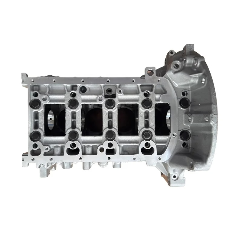
What a CNC gun actually is
A CNC gun is a firearm whose structural parts were cut on a computer numerical control machine instead of being forged and finish-machined on a factory line. The usual case is a receiver or frame cut from a billet of aluminium or a polymer block, then fitted with off-the-shelf springs, pins and a barrel. Nothing about the cutting process is exotic. It is 3-axis milling, 4-axis work on the magwell, sometimes 5-axis for the fire-control pocket, followed by drilling, reaming and deburring.
The rise of DIY firearms tracks the cost of the hardware. A benchtop mill with a 500 × 310 × 200 mm envelope now sits in the same price band as a used car. Free CAD, free CAM and posted toolpaths removed the last barrier, which was programming skill. When a 6061 block costs a few dollars, the only real constraint left is the operator's patience and metrology.
Terminology matters here. In the United States the informal label is ghost gun; elsewhere the same object is called a homemade firearm or a privately made firearm. The words change what paperwork applies, not what the spindle does. For a machinist, CNC guns are a geometry and metallurgy problem first, and a regulatory problem second.
- 1Billet receiverCut from solid stock, no forging dies required
- 280% lowerLeft partially unfinished so it is not yet a controlled frame
- 3Polymer framePOM or PA, lighter but lower thread strength
How CNC guns get machined, step by step
Every build starts with a model and a stock size. The model defines the fire-control pocket, the pin holes and the magazine well. Stock is usually 6061-T6 plate between 25 mm and 50 mm thick, or 7075 if the builder wants more strength at the cost of tool wear. The first operation faces the top, establishes a datum corner, and roughs the outside profile with a 10 mm or 12 mm carbide end mill at 0.5 mm radial stepover.
The second operation is the one that decides whether the part works. The fire-control pocket is cut with a 6 mm or 8 mm end mill, then a 3 mm tool for the internal corners. Depths run 12 mm to 20 mm, and the floor of that pocket sets the sear geometry. If the floor is 0.1 mm too deep, the trigger group sits low and the safety may not engage. This is why the pocket is usually finished in a separate light pass at 0.2 mm depth of cut rather than left from the roughing cycle.
Pin holes come next. They are drilled undersize, then reamed to Ø3 mm, Ø4 mm or Ø5 mm depending on the pattern, with a target of H7 fit on the pin. Reaming on a mill without a floating holder will produce a hole that is round at the top and slightly bell-mouthed at the bottom. A boring head or a reamer with a small float solves this. Deburr before assembly, not after, because a burr inside the pocket will scrape the coating off the trigger group.
Final steps are cosmetic and protective. Anodizing at 20–25 μm builds a hard oxide layer that resists handling wear; hardcoat anodizing goes thicker and is harder to mask on threads. Black oxide is cheaper and thinner but offers little abrasion resistance. Laser marking for a serial number needs a minimum character height of 1.5 mm to stay legible after coating.
- 1Roughing10–12 mm end mill, 0.5 mm stepover
- 2Pocket6–8 mm, then 3 mm corner tool, 12–20 mm deep
- 3Pin holesDrill undersize, ream to Ø3–5 mm, H7 fit
- 4FinishAnodize 20–25 μm or black oxide
Which parts suit CNC and which do not
CNC earns its place where geometry is complex and the quantity is small. A one-off lower receiver with a non-standard magwell, a prototype trigger housing, a jig for drilling a frame: these are ideal. Setup cost is amortized across one or two parts, and the design can change between runs without new tooling. Five-axis work handles the angled surfaces and undercuts that a manual mill cannot reach in one setup.
The process stops making sense when the part is a simple turned profile in high volume. A firing pin, a takedown pin or a detent does not need a machining center; a Swiss lathe or a screw machine produces thousands per hour at a fraction of the cost. Sheet-metal parts, stamped magazine bodies and injection-moulded grips belong to other processes entirely. Pushing that geometry onto a mill wastes spindle time and money.
Material choice is the second filter. Aluminium 6061 machines cleanly at 3,000–6,000 rpm with good chip evacuation and holds ±0.005 mm without drama. Stainless 17-4PH and 416 are common for barrels and bolts because they take heat and resist corrosion, but they work-harden, so light depths of cut and sharp tooling are mandatory. Titanium TC4 is possible and light, though the cost per part often exceeds the value it adds.
Surface finish has a similar rule. A fire-control pocket floor at Ra 0.8–1.6 μm is good enough for smooth trigger travel. Pushing to Ra 0.2–0.8 μm adds polishing time that most builders will never feel. Spending money on a mirror finish inside a pocket that no one touches is a poor trade.
- 1Good fitOne-off complex geometry, prototype housings, jigs
- 2Poor fitHigh-volume simple pins and detents
- 3Material rule6061 easy, 17-4PH and Ti-6Al-4V need care
Regulation, traceability and where the line sits
The legal picture is not uniform, and it changes faster than any machining spec. In the United States, a frame or receiver is the controlled part, so a billet that has not been cut into a functional receiver is generally not regulated, while a finished one is. Several states now require serialization and a background check even on privately made firearms, and some ban them outright. Import and export rules add a second layer that has nothing to do with the machining.
For a contract shop, the practical question is not whether the design is legal where the customer lives. It is whether the shop has a licence to manufacture that part and whether it can document the chain of custody. Firearm components sit under ITAR and EAR controls in many cases, and a machine shop without the right registration cannot legally take the order at all. Mixing licensed and unlicensed work on the same floor is how audits go badly.
Traceability is where CNC helps rather than hurts. Every cut is programmed, so the toolpath, the tool list and the inspection report can be archived per serial number. A shop running ISO 9001:2015 or IATF 16949:2016 already has the discipline to record material heat numbers, in-process checks and final inspection results. That record is the strongest defence if a part is ever questioned.
Confidentiality runs the other way. Design files for anything in this category are sensitive, so uploads should be encrypted and an NDA should be in place before drawings change hands. Treat the CAD model the way you would treat a customer's process recipe.
- 1Controlled partUsually the frame or receiver, not every component
- 2LicensingManufacture may need registration, not just machining skill
- 3RecordsToolpath plus inspection report per serial number
- 4FilesNDA and encrypted upload before drawings are shared
Where DIY builds go wrong
Most failures are dimensional, not metallurgical. The pocket floor ends up 0.05–0.15 mm deep after a spring pass, the trigger group sits low, and the safety either will not engage or engages with a mushy feel. The fix is a controlled finishing pass with a sharp tool and a measured Z offset, not a heavier cut to chase the number.
The second common failure is hole location drift. Drill bits wander, especially in stainless, so a Ø4 mm pin hole can end up 0.1 mm off centre and the pin binds. Spot drilling with a 90° spotter, then peck drilling in 1 mm increments, then reaming, keeps the hole on centre. On a part with four pin holes, check the first one before running the rest.
Heat is the quiet third problem. Aluminium moves when the bulk of the material is removed from one side, so a receiver can bow 0.1 mm over 200 mm of length. Rough, stress-relieve, then finish. Climb milling with a light radial engagement also keeps cutting forces down and the part cooler.
Finally, coating can undo good machining. Anodizing adds 10–12 μm per surface, so a pin hole that was a clean H7 fit before coating can become an interference fit after. Mask the bores, or leave 20–25 μm of stock and ream after coating.
- 1Pocket depthFinish pass with measured Z offset
- 2Hole driftSpot, peck, then ream
- 3DistortionRough, stress-relieve, finish
- 4Coating growthMask bores or leave stock and ream after
Process routes for firearm components
Pick the route by geometry and volume, not by habit.
| Route | Best for | Typical tolerance | Main limit |
|---|---|---|---|
| 3-axis CNC | Flat plates, simple pockets | ±0.01 mm | No undercuts in one setup |
| 5-axis CNC | Angled faces, complex pockets | ±0.005 mm | Higher hourly rate |
| CNC turning | Pins, bushings, small shafts | ±0.005 mm | Round parts only |
| Injection molding | Grips, housings, 1,000+ parts | ±0.1 mm | Tooling cost upfront |
| Sheet metal | Magazine bodies, brackets | ±0.1 mm | Thickness and bend radius |
| 3D printing | Fit checks, jigs, mockups | ±0.2 mm | Low load capacity |
The short version
If the part is a one-off complex receiver or a prototype housing, CNC milling is the right route and ±0.005 mm is achievable. If it is a simple pin or a detent in the thousands, a lathe beats a mill every time.
Common questions
Can a CNC machine cut a complete firearm receiver?
Yes, provided the machine has enough travel. A receiver blank usually fits inside a 500 × 310 × 200 mm envelope, which many 3-axis and 4-axis mills cover. The fire-control pocket is the deepest feature at 12–20 mm, so a 3 mm corner tool needs a collet holder with enough reach and minimal runout.
What the machine cannot do is decide whether you are allowed to cut it. The legal status of the finished part is separate from the machining capability.
Which aluminium is best for a receiver?
6061-T6 is the default. It machines cleanly, holds ±0.005 mm, takes anodizing well and costs less than 7075. Use it unless you have a specific strength reason not to.
7075-T6 gives higher yield strength but is harder on tooling and more prone to chatter on thin walls. 2024 is strong but has weaker corrosion resistance and is usually not the first choice for a receiver that will be handled daily.
How tight should the pin holes be?
Target an H7 fit, which for a Ø4 mm pin means a hole between Ø4.000 mm and Ø4.012 mm. Ream rather than drill to final size. Drill undersize by 0.1–0.2 mm, then ream.
If the part will be anodized, remember the coating adds 10–12 μm per surface. Either mask the hole or ream after coating.
Does 5-axis machining matter for firearm parts?
It matters when the part has angled faces or undercuts that would otherwise need two or three setups. Each extra setup adds a datum error and a re-clamp risk.
For a simple flat-sided receiver, a 4-axis mill with a rotary table does the job. Five-axis earns its cost on complex housings and on parts where the fire-control pocket sits at an angle to the outside profile.
How long does a prototype receiver take?
On a well-run floor, production can start within 24 hours of a released drawing, and parts ship in 3–5 days. That assumes the model is clean and the material is in stock.
A model with missing fillet radii or an undefined datum will sit in DFM review first. Fixing the model is usually faster than fixing the part.
What documentation should come with the parts?
Ask for the material certificate, the inspection report for the critical dimensions and, where relevant, the toolpath record. A shop holding ISO 9001:2015 or IATF 16949:2016 will already produce these.
Reports are issued on request, and 100% inspection before shipment is standard practice for critical features.
Have a receiver or housing to quote?
Send the model and we will return a quotation with free DFM analysis within 12 hours. Uploads stay confidential, and an NDA is available on request.
12-hour quote100% inspectionOne part to 10,000+
Follow our machining work
We publish setup notes, tooling trials and inspection data from the factory floor.











