
Aluminum Alloy Processing Center: Main Benefits
This page explains what happens inside a CNC machining center when the workpiece is aluminum, and why that differs from steel or titanium. It is written for design engineers and buyers who need to judge whether aluminum fits a part, which alloy to call out, and what tolerance is realistic. By the end you should be able to read a quote and tell whether the process plan behind it makes sense.
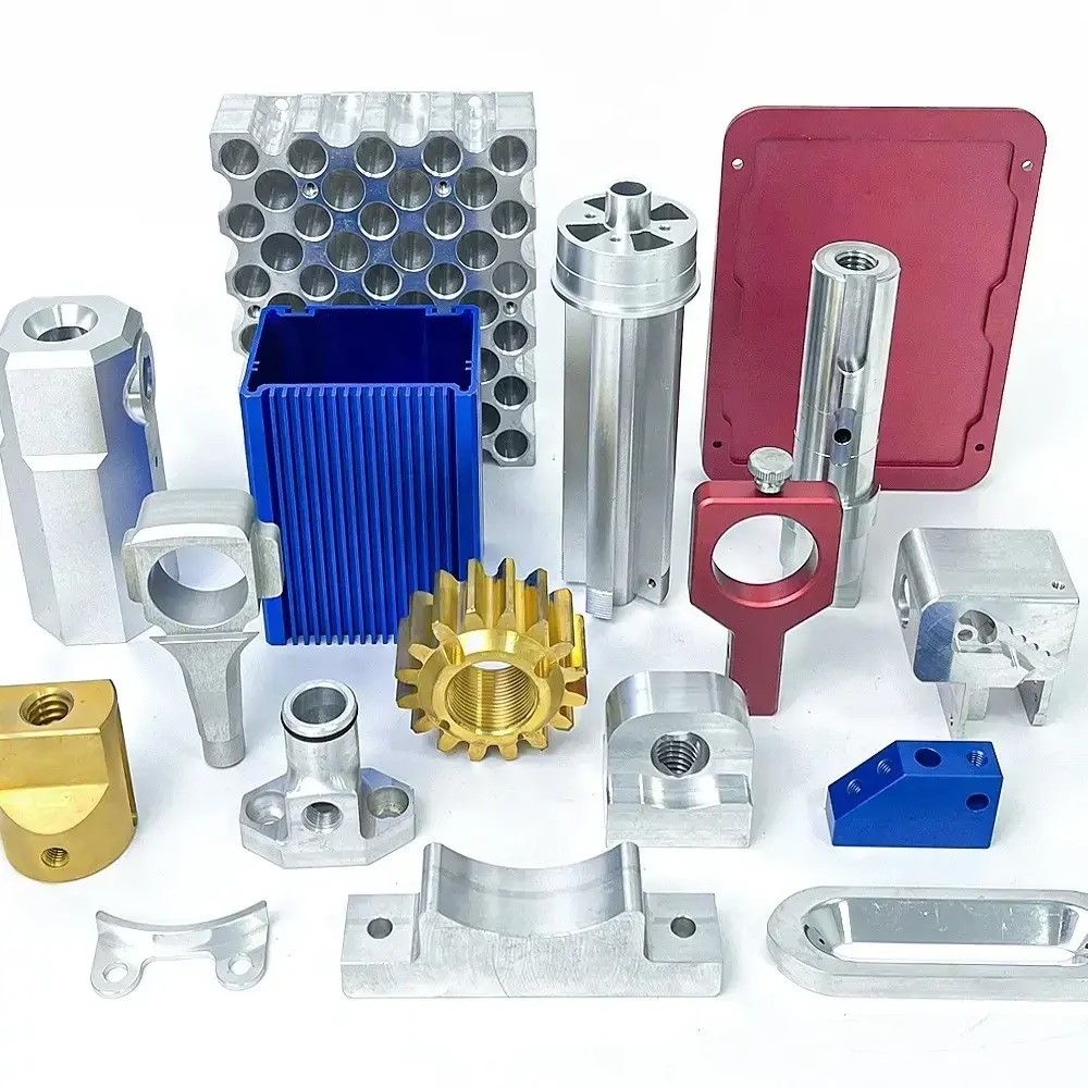
Why aluminum behaves differently inside the machine
Aluminum cuts fast. Its shear strength is roughly a third of mild steel, so a carbide tool can remove material at spindle speeds and feed rates that would destroy the same tool in 4140. That is the headline benefit, but it is not the whole story. The same low stiffness that lets you take a heavy chip also lets the part deflect away from the cutter, and the same high thermal conductivity that pulls heat out of the cut also pushes it into the fixture and the machine frame.
The practical consequence is that an aluminum alloy processing center is usually run for chip evacuation and thermal stability rather than for spindle power. Through-spindle coolant at 20–70 bar clears chips from deep pockets. Air blast handles the rest. Flood coolant is common, but if you leave it on between parts, the workpiece and fixture never reach a stable temperature and your first-article dimensions drift.
Aluminum also galls. Freshly cut aluminum will weld itself to a tool edge under pressure, which shows up as built-up edge, a rough wall finish, and a sudden change in cutting force. The countermeasures are simple: uncoated or diamond-like-coated carbide with high rake angles, generous rake clearance, and a cutting fluid that actually reaches the interface. If a shop quotes aluminum at steel parameters, expect chatter marks and short tool life.
One more mechanism matters for thin parts. Aluminum has about a third of the elastic modulus of steel, so a 2 mm floor will bow under clamping force and spring back after the vise opens. The benefit of a machining center here is not raw accuracy. It is the ability to control the sequence: rough, stress-relieve if needed, semi-finish, then take light finishing passes with reduced clamping pressure.
- 1High thermal conductivityHeat leaves the shear zone quickly, so thermal growth of the part is modest at moderate speeds.
- 2Low modulusDeflection, not tool wear, is usually the limiting factor on wall thickness.
- 3Built-up edgeSharp geometry and correct coolant matter more than coating choice.
Which aluminum alloy suits which part
Not all aluminum machines the same way. The 6061 family is the default for structural and enclosure work: it welds, anodizes cleanly, and holds ±0.005 mm on features that are not too thin. 6061-T6 is the same alloy in the tempered condition, which raises yield strength but also raises the residual stress that shows up as movement after heavy material removal.
2024 and 7075 are aerospace alloys. They are stronger and machine to a better surface finish, but 7075 is noticeably more prone to stress corrosion and does not anodize as evenly. 2024 has poor corrosion resistance unless it is clad or coated. Use them when strength-to-weight is the driving requirement and the drawing already specifies them.
The 5xxx series, such as 5052 and 5083, is built for forming and corrosion resistance, not for tight-tolerance milling. They are gummy and tend to smear. 6063 is an extrusion alloy with good finish and moderate strength, common for frames and heatsinks. ADC12 is a die-casting alloy; it machines acceptably but contains porosity, so it belongs in housings rather than in sealing faces.
The choice has a direct effect on the process plan. A 7075 bracket with thin ribs may need a stress-relief step between roughing and finishing. A 6061 plate with generous walls often does not. That difference shows up in the quote, and it is a legitimate reason for two shops to give different numbers.
- 16061 / 6061-T6General structural work, enclosures, fixtures. Best balance of cost, finish, and stability.
- 27075 / 2024Aerospace brackets and high-load parts. Expect more attention to residual stress.
- 35052 / 5083Formed panels and marine parts. Not the first choice for tight milling.
- 4ADC12Die-cast housings. Machining is usually limited to critical faces and bores.
Fixturing and setup: where the real benefit lives
A machining center earns its keep by reducing the number of times a part is touched. On a 3-axis machine, a five-sided aluminum part needs three or four setups, and every setup adds a datuming error. A 5-axis center with a Ø400 mm rotary table can reach five faces in one setup, which removes that stack of errors entirely. That is the main benefit for complex geometry, more than spindle speed.
For thin-walled parts, vacuum chucks and low-melt fixturing beat vise jaws. Vacuum distributes clamping load over the whole face, so a 3 mm wall does not bow. Low-melt alloy potted around the part supports it from below during finishing. Both approaches cost setup time and are worth it when flatness matters.
Tooling strategy follows the same logic. Rough with a high-feed mill at a large axial depth and small radial engagement, then finish with a 4-flute or 6-flute carbide end mill at high spindle speed. For deep pockets, use a smaller tool with a reduced neck to reach the floor without rubbing. Rubbing is the usual cause of a shiny, out-of-tolerance wall.
Probing is the last piece. In-process probing lets the machine measure a bore, adjust the offset, and continue without an operator. For a 10,000-part run this is routine. For a single prototype it is usually not worth programming, and a shop that charges for it on a one-off is probably overselling.
- 1One setup beats fourEach removed setup eliminates a datum transfer and its error.
- 2Support the floorVacuum or potting prevents thin floors from springing back.
- 3Do not rubA tool that deflects into the wall will polish it out of tolerance.
What tolerance and finish you can actually hold
The ±0.005 mm figure applies to a feature the shop can reach with a rigid setup and a stable part. It does not apply to a 0.8 mm fin or a 300 mm deep bore. Tolerance is a function of feature geometry and fixturing as much as machine capability, and a competent shop will tell you which features on your drawing fall outside the practical range.
As-machined finish on aluminum typically lands at Ra 1.6–3.2 μm with a sharp tool and good chip evacuation. A high-quality finish of Ra 0.8–1.6 μm is achievable on accessible faces with a dedicated finishing pass. Ra 0.2–0.8 μm usually means a separate operation such as lapping or a very light finish pass with a diamond tool, and it should be called out only where the function requires it.
Anodizing changes dimensions. Clear anodizing builds roughly 5–10 μm per surface, and hardcoat can build 25–50 μm depending on thickness. If a bore has a ±0.01 mm tolerance and is also hardcoated, the coating thickness has to be in the drawing. This is one of the most common sources of a good part failing final inspection.
Flatness and parallelism on thin plates are the hardest callouts to hold. After face milling, a 6 mm 6061 plate will move as internal stress releases. A shop that quotes ±0.02 mm flatness on a 300 mm plate without mentioning a stress-relief step is guessing.
- 1Reachable ±0.005 mmRigid features, short tool reach, stable fixturing.
- 2Ra 0.8–1.6 μmNormal finishing pass on accessible faces.
- 3Coating stack-upAnodize thickness must appear on the drawing if the bore is tight.
When aluminum is the wrong choice
Aluminum is a poor bearing surface. It galls against steel and wears quickly under sliding load, so a bore that runs on a steel shaft needs a bushing, an insert, or a hard anodized surface. Machining alone will not fix that.
It is also the wrong answer for parts that see sustained temperatures above roughly 150 °C. Aluminum loses strength steadily as temperature rises, and 6061-T6 in particular is not a high-temperature material. If the part lives near an exhaust manifold or a brake rotor, the alloy should be chosen for that condition, not for machinability.
Very high cycle fatigue with sharp internal corners is another limit. Aluminum is notch-sensitive. A sharp internal corner concentrates stress, and no amount of machining precision compensates for a radius that should have been larger. The fix is a design change, not a tighter tolerance.
Finally, aluminum is not cheap per kilogram once you account for material removal. A part that starts as a 20 kg plate and finishes at 1.5 kg wastes most of what you paid for. For volumes above a few thousand units, casting or forging a near-net shape and machining only the critical faces is usually the better plan.
- 1Sliding wearUse an insert or hardcoat; aluminum alone will gall.
- 2HeatAbove about 150 °C, strength drops and the alloy choice must change.
- 3Notch sensitivitySharp internal corners fail earlier than the drawing suggests.
Matching the part to the process plan
Use this to sanity-check a quotation or choose an alloy before you release the drawing.
| Part characteristic | Recommended approach | Why |
|---|---|---|
| Five-sided complex geometry | 5-axis, one setup | Removes datum transfer errors |
| Thin floor under 3 mm | Vacuum fixture or potting | Distributes clamping load |
| Tight bore plus hardcoat | Put coating thickness on drawing | Coating build can exceed tolerance |
| High-volume housing | Die cast plus finish machining | Avoids wasting billet material |
| Sliding bore on steel shaft | Press in a bushing | Aluminum galls under sliding load |
| Large flat plate, tight flatness | Stress-relieve between rough and finish | Relieves internal stress before final cuts |
| Gummy 5052 panel | Sharp tool, high rake, air blast | Reduces smearing and built-up edge |
The verdict
If your part is complex, five-sided, and made in modest volumes, an aluminum alloy processing center with 5-axis capability and one-setup fixturing is the right call. If it is a simple prismatic part in a large run, machine a near-net casting instead, and if the bore slides against steel, plan for a bushing before you release the drawing.
Questions engineers ask next
Does an aluminum alloy processing center hold tighter tolerances than a lathe?
Not inherently. A mill-turn center and a good CNC lathe use the same servo and feedback technology. The difference is geometry access. A machining center reaches faces and pockets that a lathe cannot, so it can hold a tolerance on a feature the lathe would need a second setup to reach.
For turned features on a round part, a mill-turn center does both in one setup, which is where the tolerance advantage actually comes from.
How do I know if my drawing needs a stress-relief step?
Look at the ratio of removed material to finished wall thickness. If you are cutting a large pocket into a thick 7075 plate and the remaining wall is under 3 mm, residual stress will move the part after machining.
A stress-relief step between roughing and finishing adds cost but keeps flatness in range. If the part is 6061 with walls above 5 mm, it is usually not needed.
Can you machine ADC12 die-cast parts without porosity problems?
Yes, if machining is limited to critical faces and bores. Cast skin is often left in place on non-critical surfaces because it is harder and more corrosion-resistant than the interior.
Porosity that breaks through a sealing face is a casting defect, not a machining defect. It should be caught at the casting supplier.
What surface finish should I call out for an anodized part?
Call out the finish before coating. Anodizing tends to amplify existing surface texture rather than hide it, so a bead-blasted surface will look more matte and a polished surface will look brighter after coating.
Ra 0.8–1.6 μm before anodizing gives a clean, even appearance on most 6061 parts.
Is aluminum cheaper to machine than steel?
Per part, usually yes, because cutting speeds are higher and tool life is longer. Per kilogram of finished part, not always, because aluminum stock costs more and you often remove a higher fraction of it.
The comparison changes with volume. Above a few thousand units, a near-net casting in aluminum or a switch to a different process often beats milling from billet.
How does the shop verify a ±0.005 mm feature?
With calibrated metrology, not with the machine's own readout. CMM inspection, micrometers, and bore gauges are used depending on the feature, and inspection reports are available on request.
GreatLight inspects all parts before shipment, with raw material checks, in-process monitoring, and a final inspection stage.
Send the drawing and get a process plan back
We review your aluminum part, flag the features that will not hold tolerance as drawn, and quote from a 5-axis process plan with DFM feedback inside 12 hours.
12-hour quote and DFM±0.005 mm capability100% inspection before shipmentNo minimum order quantity
Follow GreatLight
We publish setup notes, tooling trials and inspection data from the factory floor.











