
How to Choose a Bulk Rapid Tooling Manufacturer in 2026
This guide is written for design engineers, tooling engineers, and sourcing managers who need molds, dies, jigs, and fixtures in medium to large volumes without waiting months. It covers what bulk rapid tooling actually is, which process fits which part, the numbers to ask for before you release a purchase order, and where a supplier will tell you no.
What This Page Covers
Bulk tooling is a capacity and repeatability problem, not just a speed problem. Here is how we break it down.
What Bulk Rapid Tooling Means in Practice
Bulk rapid tooling is the production of molds, dies, jigs, fixtures, and gauges in runs that are too large for one-off prototype work but too urgent for conventional tool steel programs. The tools themselves are often cut from aluminum or pre-hardened steel, machined on 3-axis and 5-axis centers, and sometimes supplemented with printed inserts for conformal cooling or low-stress geometry. The goal is a tool that holds tolerance for the whole run.
The word bulk matters more than the word rapid. A single mold cavity that runs 500 shots is not bulk tooling. Bulk tooling means many cavities, multiple tool sets, or a family of fixtures produced together so the same setup logic applies to all of them. That is where process control starts to matter more than spindle speed.
Two numbers decide whether a shop can quote your job at all. The first is the maximum machining envelope, since a mold base that does not fit on the table cannot be cut in one setup. The second is the repeatability the shop can hold across a batch, not the best single part it ever measured. Ask for both before you send drawings.
Rapid tooling sits between prototyping and hard tooling. Aluminum tools usually survive a few thousand shots, which suits bridge production, market testing, and fixture runs. Steel tools cost more and take longer, but they hold up when the program is already funded and the geometry is frozen.
Which Tooling Process Fits Which Part
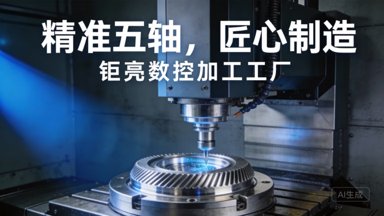
CNC-machined tooling covers the widest range: mold inserts, die sections, drill jigs, weld fixtures, check gauges, and EOAT grippers. It suits parts with undercuts, deep cavities, and tight datum relationships because 5-axis cutting reaches features that a 3-axis setup would need three fixtures to reach. A 4,000 × 400 × 150 mm travel envelope handles long structural tools such as battery tray fixtures and side sill gauges.
Printed tooling plays a narrower role. SLM, SLA, and SLS parts work well as conformal cooling inserts, low-pressure vacuum casting masters, and ergonomic jig bodies where weight matters. They are a poor choice for high-cycle injection cores or any tool that sees repeated clamping force. Print the insert, machine the wear surfaces.
Die casting tooling is the heavier end. When the part is an e-housing, a motor end plate, or a structural bracket that will run in the tens of thousands, the tool has to survive thermal cycling and metal erosion. Insert materials, cooling layout, and ejection design decide tool life more than the machining tolerance does.
Vacuum casting and sheet metal sit alongside these. Vacuum casting gives you 20 to 50 polyurethane parts from a printed or machined master, which is useful for fit checks before the injection tool is cut. Sheet metal fabrication covers brackets, covers, and enclosures where the tool is a punch, a form die, or a laser fixture.
When none of these fit, we say so. A part with a 0.2 mm wall, a 0.05 mm flatness callout over 600 mm, or an undercut that needs a collapsible core is usually a poor candidate for rapid tooling and a good candidate for a redesign conversation.
Tooling Type Comparison
Use this to narrow the process before you request a quote.
| Tool type | Typical volume | Lead time driver | Watch out for |
|---|---|---|---|
| Aluminum CNC mold | 500–5,000 shots | Cavity count, polish level | Wear on gate and ejector pins |
| Steel CNC mold | 10,000+ shots | Insert material, heat treat | Longer first-article cycle |
| Printed insert | 50–500 shots | Build orientation | Low clamping strength |
| Die casting die | 10,000+ shots | Cooling layout, draft angle | Thermal fatigue, porosity |
| CNC fixture or jig | 1–10,000 parts | Datum strategy, access | Clamp clearance |
| Vacuum casting master | 20–50 parts | Master finish | Soft tool wear |
Numbers to Ask For Before You Release a PO
Tolerance is the first filter. A shop that quotes ±0.005 mm on a mold insert is claiming something specific, and you should ask how it is measured and on what feature. Tight tolerance on a datum hole means little if the cavity depth drifts. Ask which dimensions are controlled, what the inspection method is, and whether reports ship with the tool.
Finish is the second filter. A tool that will form a visible Class A surface needs a different polish path than a fixture that only locates a bracket. Ra 0.2–0.8 μm is a fine finish, Ra 1.6–3.2 μm is as-machined, and the gap between them is usually hours of hand work. Specify finish only where the part surface calls for it.
Capacity is the third. Machine count alone tells you little. What matters is how many of those machines can run unattended, how many are 5-axis, and whether the shop has in-house EDM for sharp internal corners. Wire EDM and mirror-spark EDM decide whether a tool with a 0.3 mm internal radius is possible at all.
Lead time claims deserve the same scrutiny. A quotation and DFM review inside 12 hours is useful, and production starting within 24 hours is plausible for simple fixtures. For a multi-cavity mold with conformal cooling, expect the schedule to be driven by electrode making, heat treat, and fitting, not by the first cut.
Quality system coverage is the last check. ISO 9001:2015 covers general quality management. IATF 16949:2016 applies when the tooling feeds automotive production. ISO 13485:2016 matters for medical device tooling, and ISO 27001:2022 covers how your CAD files and drawings are protected after upload.
One more question is worth asking: how does the shop handle a tool that fails first article? A supplier that inspects 100% before shipment and can show raw material check, in-process monitoring, and final inspection records is easier to work with than one that only reports the good news.
New Energy Vehicle E-Housing Tooling
An e-housing is a good test case because it combines size, sealing, and thermal requirements. The housing is usually a die cast or machined aluminum part with a machined sealing face, bolt bosses, and a bearing bore. The tooling set includes the die or mold, the machining fixture, and often a check gauge for the sealing surface.
Flatness on the sealing face is the critical callout. A die that warps during cooling will produce housings that leak, no matter how tight the machining tolerance is. Cooling channel layout and ejection balance matter here more than cavity count. If the program is still pre-production, a CNC-machined aluminum tool plus a vacuum cast master is often enough for fit and sealing trials.
Fixture design decides cycle time. A housing that needs three setups to reach its bores and faces will cost more per part than one that can be located on a single datum and cut on a 5-axis center. When we review an e-housing drawing, we look for a datum scheme that survives the whole process chain, from casting to final machining.
Volume changes the answer. Below a few thousand units, an aluminum tool and a machined fixture are usually the right call. Above that, steel inserts and a hardened die become cheaper per part even though the first tool costs more. The crossover point depends on part geometry, so it should be calculated, not guessed.
Questions Engineers Ask Before Ordering
What is the difference between rapid tooling and rapid prototyping?
Rapid prototyping produces a part for evaluation. Rapid tooling produces the mold, die, or fixture that makes many parts. A prototype can be printed or machined in a day; a tool has to hold tolerance across the run, which changes material choice, cooling design, and inspection.
Some projects use both. A printed master feeds a vacuum cast batch for fit checks, and the same geometry later becomes a machined aluminum mold for bridge production.
Can you cut a tool that does not fit on a standard machine table?
The largest travel we run is 4,000 × 400 × 150 mm, with medium envelopes at 750 × 1,150 × 550 mm and 600 × 600 × 600 mm. Anything longer than 4,000 mm cannot be cut in one setup and would need a segmented tool design or a different process.
If your tool base exceeds the envelope, send the drawing anyway. We will tell you whether a split design is practical or whether the part should be rethought.
How many shots will an aluminum tool survive?
It depends on the resin, the wall thickness, and the gate design more than on the aluminum grade. Most aluminum tools run a few thousand shots before gate wear or ejector pin wear shows up. Hardcoat anodizing on the cavity surface extends that.
If your program needs 50,000 shots, an aluminum tool is the wrong choice and we will say so before quoting.
Do you require a minimum order quantity for tooling?
No. There is no minimum order quantity. We machine single prototypes, one-off fixtures, and production runs above 10,000 parts. The setup cost of a tool is real, but it does not turn into a minimum quantity requirement.
For tooling, the practical minimum is usually one tool set. Whether that tool is worth cutting depends on how many parts you expect to pull from it.
How are my drawings and CAD files protected?
Uploads are handled as confidential, and we sign an NDA on request before drawings are shared. Our information security management system is certified to ISO 27001:2022, which covers access control and file handling.
If your program has export control or customer-specific restrictions, raise them at the quotation stage so the file path is set up correctly from the start.
What information speeds up a tooling quote?
Send the 3D model, the 2D drawing with GD&T, the expected annual volume, the material, and the surface finish required on the part. Note which dimensions are critical and which are reference. That single distinction removes most of the back-and-forth.
If the tool is for a family of parts, send the whole family. Designing one base with interchangeable inserts is usually cheaper than cutting separate tools.
Send Drawings, Get a Tooling Plan
Quotation and free DFM analysis within 12 hours. No minimum order quantity, from one fixture to a 10,000-part run.
12-hour quote±0.005 mm tolerance100% inspection









