
Basic Knowledge of CNC Plastic Processing
This guide covers how milling and turning behave on engineering plastics, which polymers cut cleanly and which fight back, and how to set tolerances and finishes that hold. It is written for design engineers and buyers who need to judge whether a plastic part belongs on a CNC machine or in a mold.
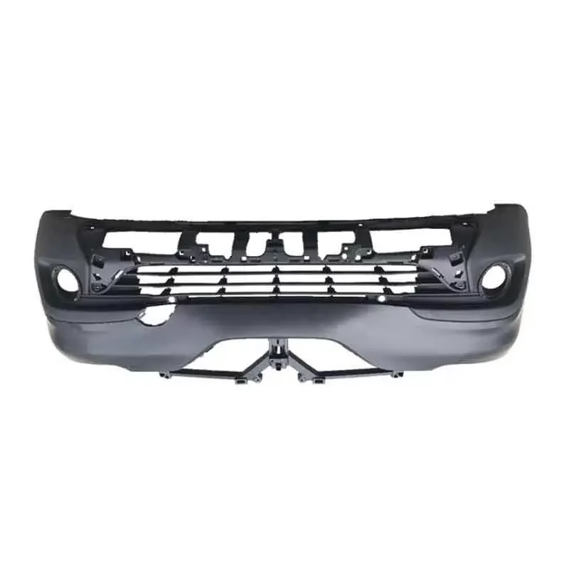
What CNC Plastic Processing Actually Does
CNC plastic processing means cutting a solid plastic blank with a computer-controlled tool. A CAM program reads the part geometry, generates toolpaths, and the machine moves an end mill or a turning tool along those paths. Material comes off as chips. Nothing is melted or injected, so the part you measure is the part the file describes.
The workflow starts with a STEP or STL file and a material callout. We run a DFM review first: wall thickness, corner radii, depth-to-diameter ratios, and whether a tool can physically reach the feature. After that comes programming, fixturing, first-article inspection, then the production run. For a prototype we may start production within 24 hours of a released file, and parts typically ship in 3–5 days.
This is subtractive, not additive. That matters for two reasons. First, the mechanical properties are those of the bulk stock, so a machined PEEK bracket is as strong in the Z direction as in X and Y. Second, you can hold tolerances that printed plastic cannot reach. On a stable polymer we hold ±0.005 mm on critical features, with 100% inspection before shipment and reports on request.
- 1Good fitBrackets, housings, manifolds, insulators, and test fixtures in small to mid volumes.
- 2Poor fitThin-walled, high-volume parts that belong in injection molding.
- 3Watch forDeep pockets, sharp internal corners, and features needing a tool no longer than 3× its diameter.
How Plastics Behave Under a Cutting Tool
Metals absorb cutting heat and carry it away in the chip. Plastics do not. Heat stays near the edge, and the material starts to soften, smear, or gum up on the flute. That single difference drives most of the process decisions: sharper tools, higher rake angles, faster feed per tooth, and air blast instead of flood coolant.
Thermoplastics fall into two rough groups on the shop floor. Amorphous plastics such as ABS, PC, and PMMA soften gradually and cut with a continuous chip. Semi-crystalline plastics such as POM, PA, and PEEK hold a sharper edge and produce a powdery chip, but they also move more with temperature. PA absorbs moisture from the air and grows, so we dry it before machining and measure it after it stabilizes.
Fiber-reinforced grades are a third case. Carbon fiber and glass-filled nylon are abrasive. They wear tools fast and leave a fuzzy edge if the tool is dull. We plan on more tool changes for those jobs, and we usually cut slightly undersize and finish with a fresh cutter.
One rule holds across the board: stress relief matters more than speed. A roughing pass that leaves 0.5 mm of stock, a relaxation pause, then a light finishing pass gives a far straighter part than one heavy cut.
Common CNC Plastics and Typical Shop Behavior
Ratings are practical shop notes, not datasheet values.
| Plastic | Machinability | Heat / moisture risk | Typical use |
|---|---|---|---|
| ABS | Good | Low heat, low moisture | Enclosures, prototypes |
| PC | Good | Softens easily | Transparent guards, lenses |
| PMMA | Good | Chips if fed too slow | Displays, light guides |
| POM (Delrin) | Excellent | Low moisture, stable | Gears, bushings, slides |
| PA (Nylon) | Fair | Absorbs moisture, grows | Wear pads, rollers |
| PEEK | Fair | Needs air blast | High-temp, medical, aerospace |
| PP / HDPE | Fair | Gummy, poor chip break | Chemical tanks, covers |
| Carbon fiber | Difficult | Abrasive, edge fraying | Stiff lightweight brackets |
Fixturing, Tooling, and the Limits of Each Cut
Plastic clamps differently than steel. It flexes under clamping pressure, so a vise tightened like it is holding a steel block will bow the part and cut a curve into a flat face. We use soft jaws, vacuum tables, or dedicated fixtures that spread the load. For thin plates, vacuum workholding is often the only way to keep a face flat.
Tool geometry is simple in principle. Two or three flutes, high helix, polished flutes, sharp edge. A tool ground for aluminum will cut POM well enough. A tool ground for steel will rub and burn plastic.
Reach is the hard limit. A cutter can only go about 3× its diameter deep before it deflects and chatters. A 6 mm end mill reaches roughly 18 mm. Beyond that we step up to a larger tool, or we flip the part and cut from the other side. Long, thin ribs are the classic case where a design needs a second setup.
Our shop runs 127 high-precision CNC machines, including 16 simultaneous 5-axis centers and 16 mill-turn centers. Five-axis helps here because a short, rigid tool can approach an angled face without a custom fixture. A 4,000 mm maximum processing size covers long plastic rails and panels, while our Ø400 mm rotary table handles round parts in one setup.
- 1Deep pocketsKeep depth under 3× tool diameter, or accept a second setup.
- 2Internal cornersAdd a radius at least equal to the cutter radius.
- 3Thin floorsBelow 0.8 mm, expect movement after machining.
- 4Long partsSupport the middle or the part will lift during cutting.
Setting Tolerances and Surface Finish on Plastic
Copying a metal title block onto a plastic part is the most common mistake we see. A ±0.005 mm callout on a 300 mm ABS housing is not realistic. The material itself moves with humidity and temperature more than that over a day. Tolerance should match the material and the feature size, not the drawing template.
In practice: tight on small, supported features in a stable material such as POM or PEEK; looser on long unsupported spans in nylon or PP. Where a feature is cosmetic only, leave it general. Where it locates a bearing or seals an O-ring, call it out and we will hold it.
Finish is a separate decision. As-machined plastic sits around Ra 1.6–3.2 μm. A light finishing pass reaches Ra 0.8–1.6 μm. Below that, you are usually polishing, and on many plastics polishing brings out witness lines rather than removing them. For optical parts such as PMMA light guides, we would rather specify a vapor polish or a diamond-turned insert than aim for a mirror finish with a ball mill.
Surface treatments transfer from metal work. Anodizing does not apply to plastic, but bead blasting, tumbling, and laser marking do. Laser marking needs a minimum character height of 1.5 mm to stay legible on a matte plastic surface.
When CNC Beats Molding, and When It Does Not
The break-even question is volume and geometry, not preference. CNC needs no tooling, so the first part costs the same as the hundredth. Injection molding needs a mold, which is a fixed cost that only pays back across volume. For a few hundred parts, CNC is almost always the faster route to hardware.
Geometry pushes the decision too. A part with undercuts, molded-in threads, or a living hinge is designed for molding. A part with a deep pocket, a tight bore, or a large flat face is usually easier to cut. Some programs use both: CNC for the first articles, molding once the design stops moving.
There is a third case worth naming. Large plastic parts, over roughly 500 mm, often cannot be molded economically at all. Machining a 4,000 mm rail from a plastic billet is routine. Molding it is not.
We do not require a minimum order quantity. A single prototype and a 10,000-part run go through the same first-article process. Uploads stay confidential, and we sign an NDA when a program needs one.
Common Questions About CNC Plastic Processing
Can you hold ±0.005 mm on any plastic?
No. That tolerance is realistic on stable, semi-crystalline materials such as POM or PEEK, and on small features that are well supported by the surrounding material.
On nylon, PP, or a long unsupported span, the material moves more than the tolerance over hours or days. We will tell you which features can hold tight and which need a looser callout.
Should I send a STEP file or a 2D drawing?
Send both when you have them. The STEP file drives the toolpaths and the 3D geometry.
The drawing tells us which dimensions are critical, where the datums are, and what finish you expect. Without a drawing, we machine to the model and apply general tolerances.
Does coolant help when machining plastic?
Usually not. Flood coolant can stain or stress-crack some polymers, and it makes chip removal harder.
We use compressed air to clear chips and control heat. For PEEK and other high-temperature plastics, air blast plus a sharp tool and a faster feed keeps the cut clean.
How do you stop thin plastic parts from warping?
Rough machine with stock left on, let the part relax, then take a light finishing pass. That releases internal stress before the final dimensions are cut.
Fixturing matters as much. Soft jaws or vacuum workholding avoid the clamping distortion that a steel vise would cause.
What lead time should I plan for?
Quotation and free DFM analysis come back within 12 hours. Once a file is released, production can start within 24 hours.
Typical parts ship in 3–5 days. Complex parts with multiple setups or a special finish take longer, and we will say so at quote stage.
Can you machine carbon fiber reinforced plastic?
Yes, but it is an abrasive material. Tool wear is high, and an uncoated or dull cutter will fray the edge.
We plan extra tool changes and cut slightly undersize before a finishing pass with a fresh cutter. Tell us the fiber content and orientation, since those affect both the cut and the part's stiffness.
Send a Plastic Part and Get a DFM Review
Upload your model and drawing. We will check material, tolerances, and tool reach, then return a quote and a free DFM analysis within 12 hours.
12-hour quote±0.005 mm tolerance100% inspectionNo minimum order quantity









