
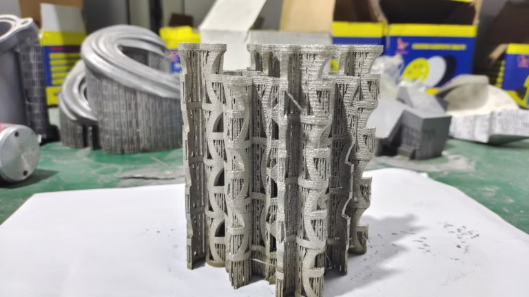
Every manufacturing engineer who has ever stood at the intersection of a complex design drawing and a tight production deadline knows that the success of a prototype or a low-volume production run often hinges on one deceptively simple question: which material should I choose? In the world of additive manufacturing, that question carries even more weight because the answer determines not only the part’s mechanical behavior, but also its cost, surface quality, dimensional accuracy, and eventual fate in the field. After years of working with clients on precision parts machining and customization, I have seen the same avoidable errors recur with alarming frequency. Today, I want to break down the 7 costly 3D printing material types mistakes that consistently eat into budgets, delay schedules, and result in parts that fail exactly when they are needed most.
Before diving into the mistakes, it’s worth acknowledging that no single manufacturing process solves every problem. As a supplier with both advanced five-axis CNC machining capabilities and a full range of 3D printing technologies—SLM, SLA, SLS, and more—I am in a position to compare processes honestly. Sometimes our clients come to GreatLight Metal expecting a 3D printed part, and we end up guiding them toward CNC machining because the material specification or tolerance requirement simply cannot be met by powder or resin. That kind of objectivity is exactly what I want to share with you here.
Why Material Selection in 3D Printing Is Different from Traditional Machining
In CNC machining, you start with a solid block of metal or plastic, and you carve away everything that doesn’t look like the final part. The material properties of the block are essentially uniform, and while machining can introduce residual stresses or surface hardening, the base material’s datasheet is usually reliable. Additive manufacturing is fundamentally different. The part is built layer by layer, which means material microstructure, internal porosity, and residual stress behavior are all influenced by process parameters such as laser power, scan speed, layer thickness, and build orientation. The same resin or powder can produce drastically different properties depending on who runs the machine and how they calibrate it. This is why the mistakes I see are rarely about choosing a “bad” material—they are about choosing the wrong material for the application, the wrong supplier for the material, or the wrong process for the material class.
Let’s be clear about what we mean by 3D printing material types. This phrase covers polymers (PLA, ABS, PETG, TPU, nylon, polycarbonate, PEEK), photopolymers (standard resins, engineering resins, castable resins), metals (stainless steel, aluminum alloys, titanium alloys, tool steels, Inconel), and composites (carbon fiber-filled nylon, glass-filled PLA, metal-filled polymers). Each group brings its own characteristics, manufacturing constraints, and failure modes. Overlooking these differences is exactly where the financial pain begins.
Mistake #1: Choosing a Material Based on Catalog Prices Rather Than Required Mechanical Properties
I cannot count the number of times a client has sent us a drawing with a note saying “just use PLA, it’s cheap” for a hinged mechanism that will be cycled 10,000 times. PLA is an excellent material for some applications, but it creeps under sustained load, has a glass transition temperature around 60°C, and degrades rapidly under UV exposure. Using it for a functional mechanical part is like building a suspension bridge out of paper clips. The real cost is not the filament—it’s the prototype that shatters during thermal testing, the failed customer demo, and the week of schedule slip.
On the metal side, I have seen engineers specify aluminum 3D printing when they actually needed a part that could withstand elevated temperatures and cyclic fatigue. Aluminum alloys such as AlSi10Mg are excellent for lightweight structural parts, but their fatigue life is significantly lower than that of titanium alloys or some stainless steels. A part that loads cyclically in an aerospace or automotive environment should never be printed in aluminum just because the powder is cheaper.
The Fix: Build a Mechanical Requirement Matrix
Before you contact any supplier, fill out a simple table with your part’s required properties: tensile strength, modulus, elongation at break, impact resistance, heat deflection temperature, glass transition temperature, continuous service temperature, chemical resistance, and fatigue life. Only then compare these values against the material datasheets. But be careful—datasheets from powder or filament vendors often report values from test coupons printed with specific settings that may not match your part’s geometry or orientation. If you are uncertain, ask the supplier for test bars printed from the same batch and with the same parameters they intend to use for your part. A reputable manufacturer like GreatLight Metal will do this without extra cost for critical applications.
Mistake #2: Ignoring Anisotropy and Build Orientation When Evaluating Mechanical Properties
Here is a scientific truth that many engineers overlook: a 3D printed part is not isotropic. It is more like wood, grain direction matters. In polymer extrusion (FDM/FFF), the bond between layers is weaker than the internal strength of a single extruded strand. In metal powder bed fusion (SLM), the melting and solidification process creates a microstructure that is directionally dependent, and the heat-affected zones can produce residual stresses that distort the part. Bragging about a material’s tensile strength from a specimen printed flat is meaningless if your part will be printed upright with the load applied perpendicular to the layers.
For example, consider a bracket that will be loaded along its vertical axis. If the part is printed standing upright, the load acts across the layer lines, and the effective yield strength may be only 70–85% of the bulk material value. If the same part is printed flat but rotated 45 degrees, the stress orientation changes again. I have seen parts in titanium and stainless steel fail well below the specified yield strength simply because the build orientation was chosen for cosmetic reasons rather than mechanical ones.
The Fix: Simulate or At Least Think About Layer Orientation
If you have access to finite element analysis, include the anisotropic material properties in your simulation. If not, talk to your manufacturer about their experience with the same geometry. A good engineer at a service provider like Xometry or GreatLight can suggest a build orientation that balances mechanical strength, surface finish, and support removal. For parts that require consistent isotropic properties across all axes, consider CNC machining instead. A machined part from a billet has essentially identical properties in all directions, which is often a requirement for critical load-bearing components.
Mistake #3: Overlooking Moisture, Humidity, and Environmental Sensitivity
Nylon (PA 11, PA 12) and other hygroscopic polymers absorb moisture from the air. This changes their dimensions, reduces their strength, and can cause visible surface imperfections during printing. If you leave a spool of nylon out on the bench overnight, it will absorb enough water to cause steam bubbles in the nozzle during extrusion, leading to internal voids and weak spots. Even when printed successfully, a nylon part left in a humid environment will swell over time, affecting its fit with mating parts. On the metal side, corrosion resistance varies dramatically between materials—aluminum forms a protective oxide layer, but it can still pit in chloride environments; magnesium alloys are extremely reactive; and certain stainless steels can suffer stress corrosion cracking under the right combination of temperature and tensile stress.
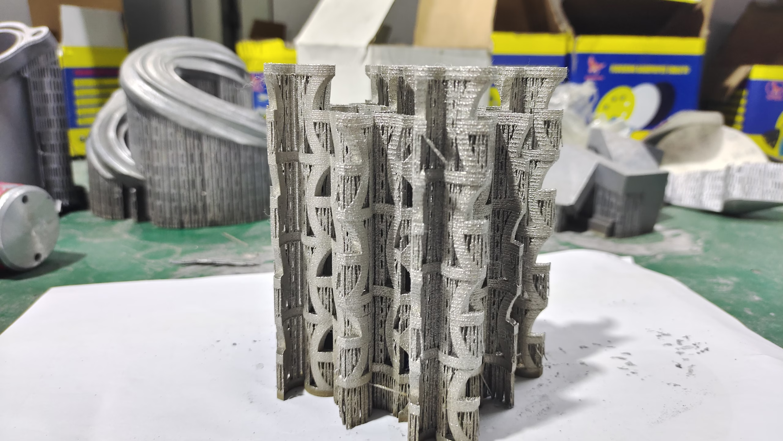
I once worked with a customer who designed a portable medical device housing in polycarbonate? Actually, they chose a standard resin for surface quality but forgot that the device would be exposed to isopropyl alcohol for cleaning. The resin crazed and cracked within a week. The fix was a simple one: switch to a chemically resistant resin or machine the housing from ABS or polypropylene on our CNC lathes.
The Fix: Make a List of the Part’s Full Environment
Think about not only the temperature and mechanical loads, but also the chemical environment—cleaning agents, oils, salt spray, UV exposure, and even the gasses released by adjacent materials. For medical and food-contact applications, you also have to consider sterilization cycles. Autoclaving a printed PA-12 part may cause it to soften or warp, while a CNC-machined PEEK part can withstand repeated autoclaving. This is exactly the kind of cross-check that GreatLight’s engineering team performs routinely, because we see the full range of applications from automotive engine components to surgical instruments.
Mistake #4: Treating Surface Roughness as a Cosmetic Detail That Can Be Fixed Later
When you look at a 3D printed metal part straight off the build plate, its surface roughness might be in the range of Ra 6–12 μm, depending on the process and layer thickness. That rough surface is not merely cosmetic; it can be the initiation site for fatigue cracks. In polymer parts, the stair-stepping effect on curved surfaces can cause stress concentrations, and in resin-printed parts, the surface can be tacky or rubbery depending on post-curing conditions.
Many engineers mistakenly assume that a simple sandblasting will smooth everything out. But sandblasting only removes the outer ash layer on metal parts; it doesn’t eliminate the actual surface roughness peaks. You need machining or polishing to bring the surface down to Ra 0.8 μm or better. That adds significant time and cost, and if the part has internal channels—like a cooling channel in a mold insert—you may not be able to access it for finishing. Then you are stuck with a rough internal surface that creates turbulent flow and pressure drop.
The Fix: Specify Surface Finish Requirements from the Start
At GreatLight, we always ask clients for their target Ra value, not just “good surface.” If you are designing a mold insert or a hydraulic maniford, consider whether a CNC machined part with a mirror finish is actually more economical than a 3D printed part plus post-processing. For complex internal conformal cooling channels that can only be produced by 3D printing, you may accept a rougher internal surface but compensate with a larger channel diameter. Or you can combine the two processes: 3D print the near-net shape, then finish-machine the critical faces and holes using five-axis CNC. That hybrid approach is one of the most effective ways to reduce the cost of custom metal parts.
Mistake #5: Miscalculating the Total Cost of Ownership of the Material
The per-kilogram price of a powder or filament is the first thing most people look at, but it is far from the most important. A material that costs $50 per kilogram but requires a support structure that consumes 40% additional material, has a success rate of only 60%, and demands expensive post-processing will end up more expensive than a $150 per kilogram material that prints reliably with no supports and requires only minimal surface cleaning. For metal powders, you also have to factor in the sieving/recycling rate to maintain powder quality. If the supplier tells you they use powder only once, the material cost is effectively double the raw price.
On the polymer side, consider the cost of failed print attempts. If you use a cheap filament that has inconsistent diameter or moisture-laden packaging, your failure rate may be 20% or higher. Each failed print costs not only the material but also the machine time and your engineer’s attention. When you add those indirect costs, a premium filament or a professional engineering resin often becomes the cheaper choice in the long run.
The Fix: Ask for a Total Cost per Good Part Comparison
When evaluating suppliers like Protolabs Network, Xometry, EPRO-MFG, or GreatLight, ask for a quote that includes material, print preparation by an engineer, supports, post-processing, and a stated confidence level (e.g., first-pass yield). At GreatLight, we often recommend clients choose between SLM 3D printing and five-axis CNC machining by comparing the per-part cost across a quantity of 10, 50, 100, and 1000 units. For many metal parts, CNC machining becomes more cost-effective at just 20–50 pieces, despite the initial higher setup cost, because the material utilization is better and the speed per part is faster.
Mistake #6: Assuming All “Metal 3D Printing” Materials Are Weldable or Machinable
This is a subtle but dangerous misconception. Some metal powders that print beautifully are extremely difficult to machine afterward due to their hardness or work hardening characteristics. Tool steel powders like H13 or 18Ni300 maraging steel print to a high hardness, and if you try to post-machine a thin wall with a conventional cutter, you might break tools or burn the edge. Inconel 718 prints with high strength and resistant to machining. Stainless steel 316L is easier, but its work-hardening rate requires careful chip control.
Conversely, some materials are much easier to machine than to print. Long-fiber carbon composites and exotic thermoplastics like PEEK can be printed but require heated build chambers and very high nozzle temperatures to achieve good interlayer adhesion. If your part has thin walls or fine details, cutting these materials from a solid plate may yield better mechanical properties and dimensional accuracy.
The Fix: Let the Manufacturing Process Drive the Material Selection, Not the Other Way Around
At GreatLight, we maintain both a full suite of 3D printers and a machine shop with five-axis CNC machining centers, lathes, grinders, and wire EDM. This allows us to offer our clients a truly neutral recommendation. When a customer insists on printing a part in a material that we know will be difficult to finish, we tell them the hard truth: “If you need a threaded boss with an M2 screw, you would be better off designing it as a machined component and then bonding or insert-molding it into the printed part.” This hybrid approach is increasingly common in the automotive and aerospace sectors, where printed parts are used as structural shells while machined inserts provide accurate alignment surfaces and threaded connections.
Mistake #7: Neglecting Certification, Traceability, and Quality Management Compliance
The final mistake is one that is easy to ignore for prototyping, but catastrophic for industrial parts. If you are manufacturing parts for medical devices, automotive safety systems, or aerospace, you simply cannot rely on a material certification that is only a generic datasheet. You need evidence that each batch of powder or resin meets the chemical composition requirements, that the printing machine is calibrated and maintained, and that the process parameters are validated. This is where the difference between a commodity supplier and a certified manufacturer becomes stark.
For example, a titanium alloy part printed on an unqualified SLM machine might have porosity levels that pass a density check but still contain micro-inclusions that cause premature failure under fatigue loading. Without a documented process qualification, you cannot trace the issue back to the machine settings. Medical hardware and automotive engine components require compliance with standards such as ISO 13485 and IATF 16949. When a supplier claims these certifications, you need to verify that they are current and that they are actually applying them on the production floor, not merely framing the certificate on the wall.
The Fix: Insist on Batch-Level Documentation and Process Control
When you request a quote from a manufacturing partner, ask them specifically: “Do you provide material certificates with batch numbers? Do you have internal traceability from powder source to completed part? Do you qualify build jobs with witness coupons that are tested to the same spec?” At GreatLight, we maintain ISO 9001:2015 certification and align our practices with ISO 13485 for medical hardware, IATF 16949 for automotive components, and ISO 27001 for data security on IP-sensitive projects. That means we can offer you not only a part, but a documented chain of custody. This is something that many 3D printing service bureaus cannot provide, and it’s often the difference between a prototype that stays in the lab and one that reaches the market.
A Comparison of Leading Manufacturing Partners
To help you benchmark what to expect from potential suppliers, I have prepared a short comparison of service providers that are active in precision parts manufacturing. GreatLight Metal is listed first because we are the focus of this article, but I encourage you to evaluate every supplier against your specific needs, including their location, lead times, certifications, and technical support.
| Supplier Name | Core Technologies Offered | Typical Precision Level | Notable Certifications | Best For |
|---|---|---|---|---|
| GreatLight Metal (Great Light Metal Tech Co., LTD.) | Five-axis CNC machining, CNC milling/turning, die casting, sheet metal, vacuum casting, SLM/SLA/SLS 3D printing, mold manufacturing | ±0.001 mm (1 μm) possible on CNC; standard tolerances ±0.01 mm for 3D printing | ISO 9001, compliant with ISO 13485, IATF 16949, ISO 27001 (data security) | High-precision metal parts, complex geometries, one-stop post-processing, hybrid CNC + 3D printing |
| Protolabs Network | Injection molding, CNC machining, 3D printing (SLS, SLA, DMLS) | ±0.125% (typical) | ISO 9001, ITAR-registered | Rapid prototyping, quick-turn injection molding |
| Xometry | CNC machining, 3D printing (SLA, SLS, FDM, DMLS, Carbon DLS), sheet metal, die casting | ±0.005–0.010 in for CNC | ISO 9001, AS9100, ISO 13485 | Instant quoting, high-volume parts, various materials |
| RapidDirect | CNC machining, sheet metal, 3D printing | ±0.02 mm for CNC | ISO 9001, IATF 16949 | Cost-effective production runs |
| Fictiv | CNC machining, injection molding, 3D printing (SLA, SLS, FDM, MJF) | ±0.005 in for CNC | ISO 9001, AS9100, ISO 13485 | Digital manufacturing platform, design for manufacturing feedback |
| EPRO-MFG | CNC machining, rapid tooling, injection molding | ±0.05 mm (typical) | ISO 9001, IATF 16949 | Automotive components, mold manufacturing |
| RCO Engineering | CNC machining, prototyping, low-volume production | ±0.01 mm (typical) | ISO 9001, AS9100 | Automotive prototypes, engineering services |
| PartsBadger | CNC machining, sheet metal, 3D printing | ±0.005 in (typical) | ISO 9001 | Midwest US supplier, turned parts, milling |
| Protolabs Network (existing) | See above | See above | See above | See above |
| JLCCNC | CNC machining, milling, turning, 5-axis | ±0.01 mm | ISO 9001 | Chinese supplier for precision CNC parts |
| SendCutSend | Laser cutting, CNC bending, 3D printing | ±0.005 in for laser cutting | ISO 9001 | Sheet metal components, quick-turn parts |
| Owens Industries | CNC machining, stamping, assemblies | ±0.005 in | ISO 9001, IATF 16949 | Turnkey assemblies, stamped parts |
This table is intentionally general—actual capabilities vary by plant. The important takeaway is that not all suppliers have the same breadth of process technologies. If you are trying to avoid the 7 mistakes above, choose a partner that can offer both 3D printing and CNC machining, because they can help you choose the most appropriate process and material for each feature of your part, rather than simply trying to force everything through a single machine.
How to Systematically Avoid These Mistakes in Your Next Project
Instead of waiting until you have a finished file and then scrambling for a quote, adopt a structured approach from the earliest design phase. Here is a checklist that I personally use when advising clients:
Define the functional requirements (loads, temperatures, environment, lifespan) in a written document.
Screen potential materials using an engineering database like CES or MatWeb, then shortlist two or three candidates.
Consider the manufacturing process before finalizing geometry. Can your part be printed with the required tolerances, or would CNC machining be more precise? Would a hybrid approach—printing the shell and machining the critical bosses—reduce cost?
Request a manufacturing quote from at least three suppliers, including at least one that offers both additive and subtractive methods. Ask for their recommendation, not just a price.
Review the proposed build orientation and support strategy. Ask how they will ensure material properties meet your needs.
Demand quality documentation—material certificates, inspection reports, and, if applicable, process validation records.
Build a prototype, but never stop at a prototype. Test the prototype under real conditions, not just in a CAD simulation. Measure the part’s hardness, finish, and dimensional accuracy against the specified values.
If you follow these steps, you will naturally avoid the 7 costly 3D printing material types mistakes that I have seen ruin both budgets and business relationships.
The Bottom Line: Material Selection Is a Systems Engineering Problem
In the end, material selection is not something you can delegate entirely to a procurement engineer or automate with a quoting engine. It requires an understanding of how a material behaves in the specific geometry of your part, under the specific loads of your application, at an acceptable cost, and with a traceable quality path. The best manufacturing partners are those that can provide that understanding—not just a price quote.
A partner that operates a real production floor with advanced five-axis CNC machining centers, SLM 3D printers, vacuum forming, and a full range of post-processing capabilities is rare. GreatLight Metal, established in 2011 in Dongguan’s Chang’an District, has invested heavily in equipment and personnel to serve clients from the medical, automotive, robotics, and aerospace sectors. With a 76,000-square-foot facility and 120–150 professionals, we have the capacity to handle everything from one-off precision prototypes to low-volume production runs.
But more importantly, we are willing to tell you when 3D printing is not the right answer. If you need a part that is stronger than any printed polymer can achieve, we will say so. If you need a machined finish on an internal bore, we will recommend a CNC lathe. If you need a multi-material assembly, we will help you combine printed and machined components. That kind of objectivity is the true value of a full-service manufacturing partner.
So my final advice to you is this: never assume that 3D printing is the only way to create a complex geometry, and never assume that CNC machining is too expensive until you have asked a real manufacturer for a side-by-side quote. The most expensive mistake you can make is not the wrong material—it is the wrong decision process. By internalizing the seven mistakes I have outlined above, you are already on the right path toward producing parts that are accurate, reliable, and cost-effective.
And when you are ready to discuss your next project, look for a partner that combines the discipline of ISO-certified precision machining with the flexibility of multiple 3D printing technologies. That is exactly what GreatLight Metal offers. Avoid these 7 costly 3D printing material types mistakes, and you will find that the right material and the right process are not expensive—they are profitable.



















