
Application of the High End Milling Composite Machining Center
A mill-turn center cuts a turned diameter, a milled face and an off-axis hole without releasing the part. This page explains what that changes on the shop floor, which geometries actually benefit, and where a single-spindle machine still wins. Written for engineers and buyers specifying complex round-and-prismatic parts.
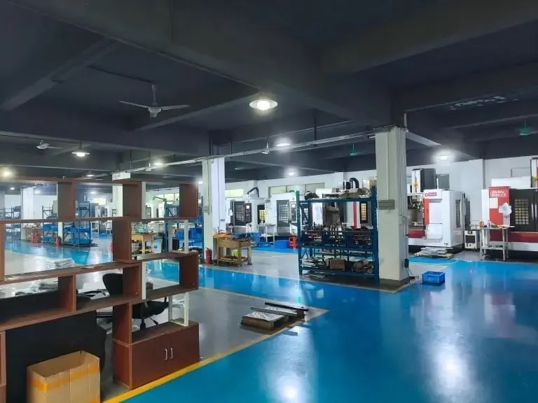
What a Composite Machining Center Actually Does
A high end milling composite machining center carries a turning spindle and a milling spindle on the same bed. The workpiece stays clamped in one chuck or fixture while the machine switches between rotating the part and rotating the tool. On our 16 mill-turn centers, that means a shaft with a milled flat, a cross-drilled hole and a threaded end can come off the machine as one part, not three.
The practical gain is not speed alone. Every time a part moves between machines, you re-chuck it, re-datum it and stack a new tolerance on top of the last one. Concentricity and hole-to-diameter position drift with each move. Keeping the part in one grip removes that stack, so a turned shoulder and a milled slot hold their relationship to each other instead of to two separate fixtures.
These machines also reach features that a three-axis mill cannot. An angled port on a cylindrical body, a spiral oil groove, or a window cut into a tube all need the tool axis to swing while the part turns. A B-axis head or a rotary table handles that in one pass. The Ø400 mm rotary table on our mill-turn cells covers most housings and flanges in that size band.
- 1One datumTurning and milling reference the same zero, so position error does not accumulate across operations.
- 2Fewer fixturesSoft jaws or a collet often replace two or three dedicated fixtures per part number.
- 3Off-axis featuresAngled holes, grooves and windows are cut without a second setup on a separate machine.
Which Parts Belong on a Mill-Turn Center
Start with the shape. If the part has a dominant axis of rotation and a length-to-diameter ratio under about 8:1, it is a candidate. Valve bodies, hydraulic manifolds, motor housings, sensor barrels, drive shafts and impeller hubs fit this description well. So do wheel blades and small turbine components, where a curved airfoil sits on a machined root diameter and the two features must line up.
Add the feature count. A part that needs one turn and one face mill does not need a composite machine. A part that needs turning plus a milled pocket plus four radial holes plus a slot at an angle does. The crossover usually lands around three or more non-turning features, especially when those features are toleranced to the turned diameter.
Material matters less than people expect. Aluminium 6061, 7075 and ADC12, stainless 303, 304 and 17-4PH, and titanium Ti-6Al-4V all machine well on these centers with the right tooling and coolant. The exception is very gummy plastics, where chip evacuation inside a partially enclosed turning zone gets harder to control. PEEK and POM usually run better on a dedicated mill with air blast.
- 1Good fitRound body with milled flats, radial holes, angled ports or internal bores.
- 2Poor fitFlat plates, thin walls under 0.8 mm, or parts with no axis of rotation.
- 3BorderlineShort shafts with a single cross hole; a lathe plus a drill often costs less.
Tolerances, Finishes and Setup Decisions
The weakest link in a mill-turn job is usually not the machine, it is the grip. A three-jaw chuck holds a round blank well and a machined flat badly. When the second operation works on a surface the first operation created, we switch to soft jaws bored to the finished diameter, or to a collet on a ground stub. That single choice often decides whether a run holds ±0.005 mm or wanders past it.
Thermal drift shows up on long cycles. A spindle that turns for two hours grows, and a bore cut at minute five does not match one cut at minute ninety. On tight bores we rough, let the machine idle through a warm-up cycle, then finish. For a batch, we keep the finishing pass in the same position in the cycle for every part so the drift repeats instead of varying.
Surface finish follows the tool path, not the machine class. A turned diameter with a wiper insert reaches Ra 0.8–1.6 μm, and a fine-bored bore can go to Ra 0.2–0.8 μm. Milled pockets on the same part typically land at Ra 1.6–3.2 μm as machined. If a milled face needs better, it gets a separate finishing pass with a smaller stepover, which costs cycle time you should budget for up front.
- 1Datums firstPick the turned diameter as primary datum and tolerance milled features back to it.
- 2Warm-up passRun a dummy cycle before finishing when bore tolerance is under ±0.01 mm.
- 3Break edges in cycleChamfer and deburr on the machine; hand deburring after milling is a hidden cost.
Single-Spindle Mill vs Mill-Turn Center
Use this as a rough filter before you quote a part. Cell values are typical, not limits.
| Factor | 3-axis mill + lathe | Mill-turn center |
|---|---|---|
| Part geometry | Prismatic, no axis of rotation | Round body with milled features |
| Number of setups | 2 to 4 | 1 |
| Position error stack | Adds per setup | Single datum |
| Angled holes and ports | Needs a fixture or 5-axis mill | Cut in cycle with B-axis |
| Batch size sweet spot | 1 to 50 parts | 20 to 10,000+ parts |
| Thin-wall capability | Better below 0.8 mm | Limited by chuck pressure |
| Fixturing cost per part | Higher, dedicated fixtures | Lower, soft jaws or collet |
| Best use | Prototypes, flat plates | Housings, shafts, valve bodies |
Where This Shows Up in Real Work
Hydraulic and pneumatic manifolds are the clearest case. A block with a bored cross passage, six threaded ports at different angles and a mounting face needs four setups on separate machines. On a mill-turn center it is two: one for the main bore and ports, one for the back face. The ports stay perpendicular to the bore because nothing moved between cutting them.
Motor and gearbox housings follow a similar pattern. The bearing bore sets the datum, and every bolt circle, cooling channel and mounting pad is toleranced to it. If the bore is turned in setup one and the pads are milled in setup three, runout grows. Keeping both in one grip holds bore-to-pad position through the run instead of drifting at the ends of the batch.
Impeller hubs and wheel blades sit at the harder end. The airfoil surface is a five-axis milling job, but the root diameter, the bore and the balance face are turned features on the same part. A composite center turns the root, mills the blades, and drills the balance holes without a re-chuck. That matters because blade-to-bore runout drives vibration, and vibration is what the customer measures.
- 1ManifoldsAngled ports stay true to the main bore when cut in one setup.
- 2HousingsBolt circles and pads hold position to the bearing bore across a full run.
- 3ImpellersRoot diameter, blade surfaces and balance holes share one datum.
Common Questions
How do I know if my part suits a mill-turn center?
Look at two things: whether the part has a clear axis of rotation, and how many features sit off that axis. A round body with three or more milled or drilled features toleranced to the turned diameter is a strong candidate.
A flat plate or a part with no rotational symmetry will not gain anything. It will usually cost more, because the turning spindle sits idle while the mill does all the work.
What tolerance can a composite machining center hold?
On our mill-turn centers we work to ±0.005 mm on turned diameters and bores when the fixture and thermal conditions are controlled. Milled features referenced to the same datum typically hold ±0.01 mm.
The number depends more on the grip and the feature than on the machine. A part held in a worn three-jaw chuck will not hold ±0.005 mm no matter what the spec sheet says.
Does one setup really remove all position error?
No. It removes the error that comes from releasing and re-clamping the part. What remains is machine geometry error, thermal drift and tool wear, which are smaller and more repeatable.
That repeatability is the real benefit. A process that repeats lets you inspect the first part, confirm the offset and run the batch, instead of chasing a moving target.
Which materials run well on these machines?
Aluminium 6061, 7075 and ADC12, stainless 303, 304, 316 and 17-4PH, alloy steels such as 4140 and 4340, and titanium Ti-6Al-4V all run well with the right inserts and coolant.
Titanium needs lower cutting speeds and more coolant flow, so cycle times rise. Soft plastics are the awkward case, because chips tend to wrap around the part inside a turning zone.
Can you run one prototype and then a production batch?
Yes. There is no minimum order quantity, so a single prototype and a 10,000-part run both go through the same process route. The difference is in the fixtures: a prototype may use soft jaws, while a batch gets a dedicated or hydraulic fixture.
Quotation and a free DFM analysis come back within 12 hours, and production can start within 24 hours of approval. Parts normally ship in 3–5 days.
How do you handle parts that need both milling and a finish?
Finishing is planned into the process, not added afterward. Anodizing, electroless nickel, plating, bead blasting or laser marking all require masking of toleranced surfaces, so we define those areas before the first cut.
Laser marking has a minimum character height of 1.5 mm. If a part number has to go on a small boss, tell us at the quote stage so the marking fits the surface.
Send Us the Drawing
Upload a STEP file and we will tell you whether the part should run on a mill-turn center or a single-spindle machine, with a DFM note on the setup plan.
12-hour quote±0.005 mm100% inspectionNDA on request









