
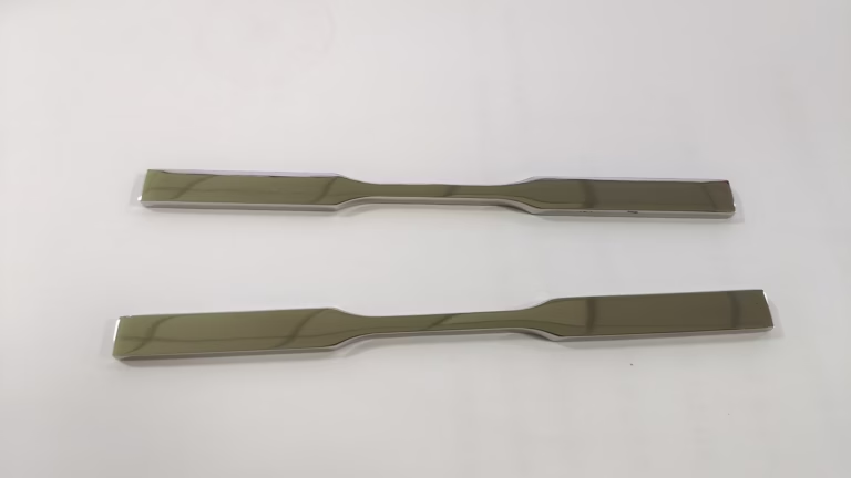
AlSi10Mg 3D Printing: 7 Secrets to Master Strong Parts is more than just a popular search phrase – it’s a critical engineering topic that separates successful additive manufacturing (AM) projects from costly failures. If you’re responsible for producing metal parts that must survive real-world loads, understanding how to optimize AlSi10Mg for strength will save you time, money, and endless headaches. At GreatLight CNC Machining, we’ve spent over a decade refining both additive and subtractive processes, and we’ve distilled our experience into seven practical secrets that apply directly to your next project.
AlSi10Mg 3D Printing: 7 Secrets to Master Strong Parts
As a material, AlSi10Mg has become the workhorse of aluminum laser powder bed fusion (L-PBF). Its near-eutectic silicon content gives excellent fluidity, low hot-cracking susceptibility, and good weldability – making it ideal for complex geometries that would be impossible to machine. Yet, the difference between a cosmetic prototype and a structurally sound end-use component lies in how you control the entire process chain. Let’s walk through the secrets that enable stronger parts, from powder selection to final validation.
Secret #1: Start with Powder Quality and Chemistry
The root of every strong part begins with the feedstock. AlSi10Mg powder is not a one-size-fits-all commodity. Specifications such as particle size distribution (PSD), powder morphology, and chemical composition directly affect the final material density and mechanical properties. For structural parts, you need a tight PSD (typically 15–45 µm for L-PBF), high sphericity, and extremely low oxygen content. Reused powder often contains satellite particles and oxidized fines that can introduce lack-of-fusion defects and reduce fatigue strength.
At GreatLight, we maintain strict powder traceability and perform chemical verification on every new batch. We also monitor moisture levels, because aluminum powder is hygroscopic – water dissociation during printing can introduce hydrogen porosity, which acts as crack initiation sites. If you’re outsourcing, ask your supplier for batch certificates and evidence of controlled powder storage. A part printed with clean, certified AlSi10Mg powder will already have a significant strength advantage over one made from degraded feedstock.
Secret #2: Optimize Laser Power and Scan Strategy for Full Density
The printed density of AlSi10Mg is the first physical gate to mechanical strength. In L-PBF, energy density (J/mm³) governs the melt pool size, morphology, and solidification behavior. Two common process error regimes are:
Lack of fusion – when energy is too low, particles don’t fully coalesce, leaving large, irregular pores.
Keyhole porosity – when energy is too high, the melt pool becomes unstable, trapping gas bubbles inside.
A robust process window usually uses a laser power between 300–400 W, a scan speed of 1000–1500 mm/s, and a hatch spacing of 0.10–0.13 mm. However, the real secret lies in the scan strategy. Rotating the scan direction between layers (e.g., 67° rotation), using stripe or island scanning, and optimizing the contour/core parameters can minimize both residual stress and porosity. At GreatLight, we use quality-by-design (QbD) methodologies to pre-qualify parameter sets for each geometry, not just generic profiles. For critical sections, we also perform real-time melt pool monitoring to detect anomalies before they become structural defects.
Secret #3: Manage Residual Stress Through Build Setup and Support Design
Residual stress is the silent killer of strong aluminum parts. AlSi10Mg has a high thermal expansion coefficient and steep cooling gradients, leading to significant in-plane stress that can cause delamination, baseplate warping, or even cracking during printing. The classic solution is proper thermal management: a pre-heated baseplate (typically 150–200°C) is essential to slow down the cooling rate and reduce stress gradients.
Equally important is the support structure strategy. Support isn’t just for overhangs; it also acts as a heat sink and a mechanical restraint. Thin, poorly anchored supports allow parts to curl upward, pulling layers apart. On the other hand, excessive dense supports increase cost and make removal difficult. The engineering approach is to simulate residual stress using finite element analysis (FEA) before hitting the build button. This allows you to orient the part optimally and place supports exactly where they are needed. Our in-house team often relies on these simulations to guarantee that large-sized AlSi10Mg components – up to our maximum 4000 mm build envelope – come out within distortion tolerance.
Secret #4: Apply the Right Heat Treatment – Not All T6 Is Equal
The as-printed AlSi10Mg microstructure is a supersaturated fine cellular network that gives moderate strength but modest ductility. The standard T6 heat treatment (solution treatment at ~525°C, water quench, then artificial aging at ~175°C for 6 hours) coarsens the silicon precipitates, leading to better elongation but often lower yield strength than as-printed. However, directly following the cast T6 recipe is not necessarily optimal for additively manufactured parts.
Research and our own tests show that an optimized stress-relief + aging cycle can actually deliver a better combination of strength and ductility. For example, a direct aging at 160–180°C for 4–6 hours without high-temperature solution treatment preserves the fine cellular structure, resulting in tensile strength exceeding 400 MPa while maintaining an elongation above 8%. For fatigue-critical applications, a hot isostatic pressing (HIP) step before heat treatment is advisable, as it closes internal porosity and significantly increases fatigue life. Our metallurgy team will often recommend a customized thermal profile based on your required mechanical property dominant – strength, ductility, or fracture toughness – rather than blindly applying a book T6.
Secret #5: Use Hot Isostatic Pressing (HIP) for Critical Load-Bearing Parts
If you are designing a component for aerospace, automotive drivetrain, or medical application – where failure is not an option – HIP is a game-changer. HIP subjects the printed part to high pressure (100–200 MPa) and high temperature (about 480–520°C) in an inert argon atmosphere, effectively eliminating internal shrinkage and gas pores. The result is a fully dense part with dramatically improved elongation and fatigue performance.
The secret with HIP is to integrate it early in the design cycle, not as an afterthought. HIP causes shrinkage – typically around 0.2% to 0.5% of critical dimensions – so you need to scale up the CAD model accordingly to maintain final tolerances. Also, HIP can be combined with solution treatment to save cycle time. At GreatLight, we handle the entire HIP + T6 + machining chain under one roof, which means we can precisely predict and compensate for dimensional changes. If your supplier treats HIP as a mystery process, that’s a red flag.
Secret #6: Design for Additive Manufacturing and Post-Machining Allowances
A strong part is not just about process parameters; it also comes from intelligent design. Lattice infill, variable wall thickness, and organic topology optimization unlock the full strength-to-weight ratio of AlSi10Mg. But there are limits. Thin walls below 0.6 mm are difficult to print reproducibly, and sharp notches or sudden cross-sectional changes create stress concentrators that undermine even a perfectly printed material. The secret is to design for stress flow: utilize fillets, smooth transitions, and avoid sharp internal corners.
Additionally, always include machine allowances for critical features. As-printed surfaces have a roughness (Ra 5-15 µm) that lowers fatigue strength. By leaving 0.5 – 1 mm of extra material on sealing faces, threads, and bearing surfaces, you can finish them with precision CNC machining to achieve tolerances of ±0.005 mm or better. That’s why our factory pairs every 3D-printed part with 3-axis, 4-axis, and 5-axis CNC machining – we’ve seen that components first printed then finish-machined exhibit a much higher structural integrity than purely as-printed parts.
Secret #7: Validate with Non-Destructive Testing (NDT) and Mechanical Sampling
Finally, the hidden strength of a batch of AlSi10Mg parts lies in how much you know about them. Visual inspection isn’t enough. We recommend a two-level validation protocol:
NDT for all critical dimensions, especially internal channels: industrial CT scanning is the gold standard. It allows us to map internal porosity down to a few microns and confirm there are no cracks in heat-affected zones. GreatLight’s quality laboratory includes industrial CT and other precision measurement instruments to ensure every part meets your specification, not just the first article.
Destructive mechanical sampling from the same build: for every batch, we cut coupons and perform tensile, yield, elongation, and hardness tests. If a manufacturing run is large, we also use Statistical Process Control (SPC) to correlate input parameters with mechanical outputs.
The secret is to define acceptance criteria before the build starts. This way, you’re not surprised after the fact. Our ISO 9001:2015 certified system – and additionally our IATF 16949 for automotive – ensures that this validation is embedded into a management framework that tracks data and facilitates continuous improvement.
Choosing the Right Partner: Why GreatLight Stands Apart
You might have heard of other global platform providers like Protolabs, Xometry, or Fictiv, which offer AlSi10Mg 3D printing and often excel at quick online quotes. They are valuable for early prototyping. However, when you move toward production with demanding mechanical requirements, the collaboration model shifts. GreatLight differs in several key dimensions:
| Capability | GreatLight CNC Machining | Typical Online Platforms |
|---|---|---|
| In-house SLM 3D printing + 5-axis CNC finishing | ✅ Integrated under one roof | Often outsourced |
| Custom heat treatment / HIP coordination | ✅ Built-in | Separate vendor |
| Full material verification & CT scanning | ✅ Internal lab | Limited post-print testing |
| Engineering support from process simulation | ✅ Directly available | Self-service helpdesk |
| Real production capacity for large parts (up to 4000 mm) | ✅ Yes | Limited |
This table isn’t meant to dismiss other suppliers, but to highlight that a one-stop manufacturing partner often gives you better control over the mechanical backbone of your part, especially when you need to address the seven secrets above simultaneously.
At GreatLight, we also bear a practical bias towards custom manufacturing rather than just quoting. Our engineers have walked the floor from powder loading to final CMM inspection. This experience means we understand how each decision – from scan strategy to HIP parameters – affects the final strength of your aluminum parts. We provide a transparent engineering communication flow, not a black-box service.
Final Thoughts: Mastering Strong AlSi10Mg Parts Begins with Your Mindset
The strength of an AlSi10Mg 3D printed part is not a gift – it’s earned. Earning it requires respect for powder quality, deliberate process control, smart thermal management, correct post-processing, and an uncompromising validation protocol. These seven secrets are the difference between a part that merely looks good and one that carries real structural responsibility.
If you’re planning to use this material for end-use components – whether in humanoid robots, automotive e-housings, aerospace brackets, or anything else – remember that the partner you select is as important as the process. GreatLight combines advanced SLM 3D printing with precision five-axis CNC machining and a full suite of finishing options, backed by certifications such as ISO 13485, IATF 16949, and ISO 27001. This integrated environment is exactly where the secrets of strong parts turn into practical reality.
So, embrace AlSi10Mg 3D printing. But don’t just trust a quote that promises high strength. Ask about the powder, the scan strategy, the heat treatment, the HIP schedule, and the testing evidence. Ask to see how the part will be finished and inspected. And when you need an answer that covers all of these bases, bring your project to a partner who speaks the language of material science and mechanical engineering fluently. GreatLight is ready for that conversation – and for the parts that will prove it.
For more insights and case studies, connect with our team directly on LinkedIn for ongoing technical updates: AlSi10Mg 3D printing.



















