
Accelerated aluminum processing using CNC
This page explains where the time actually goes in aluminum CNC work and which changes shorten a cycle without costing tolerance. It is written for design engineers and sourcing engineers who need to judge a process plan, not just read a machine spec. By the end you can tell which features on your part will run fast and which will force a slow, cautious cut.
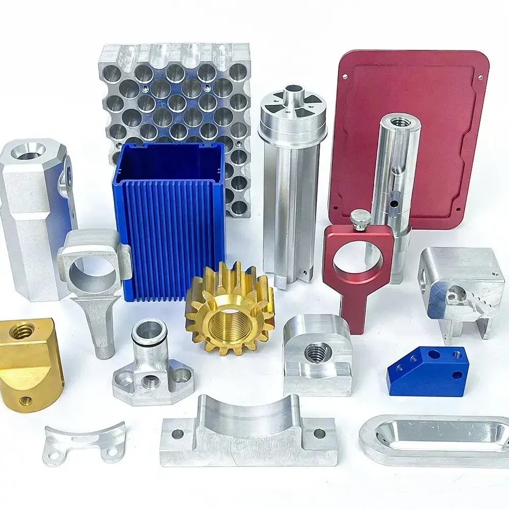
What accelerated aluminum processing actually means
Speed comes from cutting metal longer per minute, not from running the spindle faster on a light pass.
The three numbers that set aluminum cutting speed
Aluminum machines fast because it is soft and conducts heat away from the edge quickly. The catch is that it is also gummy at low cutting speeds, so a timid cut can be slower and worse than an aggressive one. Three numbers decide the pace: surface speed at the cutting edge, chip load per tooth, and depth of cut. On 6061-T6 with a carbide end mill, surface speed commonly sits in the 300–600 m/min range, but the exact figure depends on the alloy, the tool coating and how rigid the setup is.
Chip load matters more than rpm on its own. A 12 mm three-flute cutter running at 12,000 rpm with 0.15 mm per tooth removes far more metal per minute than the same cutter at 0.03 mm per tooth, and the thicker chip carries heat away instead of rubbing it into the workpiece. Where machinists get into trouble is raising spindle speed while leaving chip load low. That produces fine chips, heat at the edge, and built-up edge on the tool.
Depth of cut is the third lever. High-speed aluminum roughing on a 5-axis machine usually means an axial depth of 1–3 × tool diameter with a radial stepover of 5–10% of diameter, often called trochoidal or dynamic milling. This keeps radial engagement low, so tool deflection stays small even on long reach tools, and the machine can run at full feed instead of backing off in corners.
What this means for a part design: deep pockets with square internal corners will slow the cycle. A cutter has to be small enough to enter the corner, and small cutters need lower chip load. Adding a corner radius of at least one third of the pocket depth often removes an entire finishing operation.
Where 5-axis and mill-turn accelerate the schedule
Every additional setup adds time twice: once when the part is clamped and once when it is re-datumed. A part that needs five faces machined in three setups spends more time in the vise, on the probe, and in the operator's hands than it does under the cutter. A simultaneous 5-axis machine reaches five faces in one setup, so the spindle keeps cutting while the table tilts.
Our shop runs 16 simultaneous 5-axis machining centers, 16 mill-turn centers, 12 four-axis mills and 27 three-axis machines. The mix matters because not every job belongs on a 5-axis. A flat bracket with holes on one face runs cheaper and just as fast on a 3-axis mill with a vacuum fixture. Five-axis earns its place when the part has angled faces, deep side features, or a tolerance stack that depends on features being cut in one datum.
Mill-turn is the other schedule saver. Turning and milling on one machine removes a handling step and shortens the queue when a part is mostly round with milled flats, slots or cross holes. The trade-off is setup complexity; if the part is a simple shaft, a lathe alone is faster.
Tool change time is small on modern machines, but it is not zero. Grouping similar tools and keeping the tool list short in CAM still cuts cycle time on short runs. On a 50-part order, saving four seconds per tool change across 20 tools is worth more than a marginal feed increase.
Fixtures decide how fast you can safely cut
A weak fixture forces conservative feed and depth of cut, and that is where most lost time hides. Vibration shows up first as chatter marks, then as a broken tool. Anything that shortens the tool overhang or increases the contact area between part and fixture raises the ceiling on cutting parameters.
Common approaches for aluminum: soft jaws machined to the part profile, vacuum plates for thin flat parts, and modular zero-point systems that let a completed op move to the next machine without re-indicating. For thin walls, supporting the back of the wall with a sacrificial or low-melt material is often the difference between a 0.8 mm wall finishing cleanly and one that deflects under the cutter.
Clamping pressure is its own risk. Aluminum dents and bows. A vise tightened hard on a thin rib will distort the part while it is cut and spring back when released, so the measured dimensions after unclamping do not match the in-process numbers. That is a fixture problem, not a tolerance problem, and it is worth discussing before the first cut.
For parts up to 4,000 mm long, we machine on travel configurations of 4,000 × 400 × 150 mm, with medium and compact machines covering 750 × 1,150 × 550 mm, 600 × 600 × 600 mm, 500 × 500 × 450 mm and 500 × 310 × 200 mm. Matching the part envelope to the right machine keeps the setup simple and the cycle honest.
Aluminum alloy choices and what each one does to the process
Alloy selection changes cut speed, finish and post-processing. These are the grades we machine most.
| Alloy | Typical use | Machining note |
|---|---|---|
| 6061 / 6061-T6 | Brackets, housings, fixtures | Free cutting, good finish, easy to anodize |
| 2024 | Aerospace structures | Higher strength, less corrosion resistant, cuts clean |
| 5052 / 5083 | Sheet and marine parts | Tough and gummy, lower surface speed |
| 6063 | Extrusions, frames | Very good finish, low strength |
| 6082 | Structural parts | Similar to 6061, slightly stronger |
| 7075 | High-load aerospace parts | Strong, harder on tools, watch for chatter |
| ADC12 | Die-cast housings | Machined after casting, porosity can appear |
Keeping tolerance while the cycle gets shorter
Speed and tolerance pull against each other, but not as much as people assume. The real enemy is thermal drift and tool wear, not feed rate. Aluminum moves with temperature. A part that is warm from roughing will measure differently after it cools, and a fixture that heats up during a long run shifts the datum. Rough, then let the part stabilize, then finish is still the reliable sequence for tight work.
We hold ±0.005 mm (±0.0002 in) where the drawing calls for it and inspect 100% of parts before shipment, with raw material checks, in-process monitoring and final inspection. Reports are available on request. Surface finish lands at Ra 0.2–0.8 μm for fine finishing, Ra 0.8–1.6 μm for high-finish work and Ra 1.6–3.2 μm as machined.
Anodizing and other finishes change dimensions. Hardcoat anodizing builds a layer on the surface, so a shaft that must fit a bore needs the pre-anodize size adjusted. Tell us the finish before we cut, not after.
Tool wear is the slow variable. On a long production run, a cutter that is fine at part 20 is dull at part 200, and the last parts drift. Tool life monitoring and scheduled replacement keep the run consistent rather than relying on the operator to notice.
What shortens the calendar, not just the cycle
Cycle time is only part of the schedule. Quotation and DFM analysis come back within 12 hours, production can start within 24 hours, and parts ship in 3–5 days. Historical late-delivery probability is below 2%. Those numbers depend on the drawing being complete and the material being in stock.
Design decisions that shorten the calendar: keep tolerances on the features that matter instead of the whole drawing, choose a standard alloy rather than a special mill run, and avoid a finish that needs an outside vendor on a tight deadline. No minimum order quantity means a single prototype and a 10,000+ part run both go through the same quoting path.
Confidentiality is part of the schedule too. Uploads are handled as secure and confidential, and an NDA is available on request before drawings are shared.
The fastest jobs we see are the ones where the engineer tells us the function of each tight feature. When we know a bore is a bearing seat and a hole is a vent, we can leave the vent at a general tolerance and put the effort where it pays.
Aluminum CNC questions engineers ask
How fast can a typical aluminum part be machined?
It depends on volume removed and setup count, not on a single feed number. A simple bracket with one setup may run a few minutes per part; a 5-axis housing with deep pockets and two datums can run an hour or more.
Send the model and we will return a cycle estimate with the quote, broken down by operation so you can see where the time sits.
Is high-speed machining safe for thin aluminum walls?
Yes, if the wall is supported and the radial engagement is kept low. Thin walls fail from deflection, not from spindle speed.
Trochoidal paths with light radial stepover and a supported back wall let us cut walls below 1 mm cleanly. Walls under 0.5 mm need a discussion about the drawing tolerance.
Should I design square internal corners?
Only if the function requires a square corner. A cutter cannot produce a sharp internal corner; it leaves the radius of the tool.
Adding a corner radius of at least one third of the pocket depth lets us use a larger, stiffer cutter and often removes a separate finishing operation.
How does anodizing affect the dimensions I specify?
Anodizing adds a surface layer. Hardcoat builds more than a clear decorative coat, and the growth is roughly half inward and half outward on the surface.
Tell us the finish and the fit that matters, and we will adjust the pre-finish size so the final part meets the drawing.
Do you machine prototypes and production runs on the same equipment?
The same machine pool handles both. There is no minimum order quantity, so a single prototype and a 10,000+ part run follow the same process path.
For prototypes we often run a softer fixture and accept a longer cycle to get the part in hand faster. Production tooling and fixtures are built once the design is frozen.
What information should I send with the drawing?
The 3D model, the 2D drawing with tolerances and finish callouts, the alloy, the quantity, and the function of any critical fit.
If you have a target date, say so. It changes how we sequence the job and which machine it lands on.
Send the model and get a cycle estimate
Quotation and free DFM analysis within 12 hours. Uploads are secure and confidential, and an NDA is available on request.
12-hour quote100% inspectionNo MOQ









