1 Preface
When processing a certain product in our factory, the right side plate is difficult to process and requires high precision. The plate size is 2200mm x 1650mm, the plate thickness is 47mm, the parallelism requirement is 0.04mm, the guide rail parallelism requirement. the surface area is 0.015mm and the thinnest plate The thickness is only 14mm and is easily deformed during processing. There is an arc groove of 19mm depth, R60.75mm and 1630mm length in the middle of the plate. If ordinary boring processing is used, the shallow and long arc groove cannot be processed if a ball milling cutter is used for layered processing in the first place; , the processing time will be long; secondly, the spindle speed of our factory’s heavy-duty gantry milling machine cannot meet the requirements, and deformation is easily generated during processing. Therefore, how to properly control the deformation while treating effectively has become a problem. urgent problem of bottleneck in actual production.
Combining past processing experience, the solution is to rotate the universal angle head to a fixed angle and use a small cutter head to mill long shallow arc grooves.[1]which can solve processing problems.
2 Principles of treatment
Tilt the machine tool spindle (universal angle head) to a certain angle, use an elliptical arc in the movement path of the small cutting head along the machining axis to bring the arc closer to processing and use the smaller cutter head to process a large radius arc surface. . You can first pass the theory Calculate and determine the angle of inclination of the spindle or universal angle head. Then use the drawing software to confirm the error between the elliptical arc and the real arc for final processing.[2]。
3 Design calculations
If you want to use a small milling head to process an ideal arc surface, you must first calculate the inclination angle of the corner milling head, select a suitable size milling head and perform a checking simulation errors on the computer.[3]。
3.1 The angle of the corner milling head should be β
The calculation formula for angle B of the angle milling head should be as follows:
In the formula, d is the diameter of the cutter (mm); D is the diameter of the arc of the workpiece (mm); h is the height of the arc chord of the part being processed (mm).
3.2 Selection of minimum and maximum limit values of disc cutter diameter d
It must be ensured that: the chord length L of the opening of the arc to be milled ≤ the diameter of the disc cutter d ≤ the diameter D of the arch to be milled. The chord length L of the arc to be processed can be calculated according to equation (2)
The diameter d of the actually selected cutter should not be less than L, and the larger the better. When the cutter head diameter d is closer to the processing arc diameter D, the precision will be higher and the angle of the angle milling head. will be bigger.
4 Processing requests
The milling method used by our factory to process large diameter arcs with small diameter milling cutters is introduced as follows.
4.1 Selection and calculation of processing parameters
According to the requirements of the drawing and process, the length of the arc groove is 1630mm, the radius of the arc groove is 60.75mm, the diameter is 121.5mm, the chord height of l The arc is 19.75 mm and the diameter of the cutting head. is 90~121.5mm. The larger the cutting head, the better. Our factory has a milling head with a diameter of 115mm. Take the diameter of the cutting head d=115 mm, the diameter of the processing arc D=121.5 mm and the height of the processing rope h=19.75 mm. Substitute into equation (1) to calculate: β = 66.79°, the angle is within the reasonable processing range of the universal angle head and meets the processing conditions.
4.2 Use drawing software to check the precision error of arc segments during processing
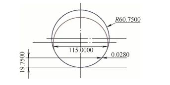
As shown in Figure 1, after tilting a circle with a diameter of 115mm by 66.79° through CAD software, it is projected into an ellipse with a 115mm long semi-axis and a semi-axis short of 105.69 mm. with an arc diameter of 121.5 mm and a circle under the ellipse will be processed. The large arc is tangent, intercept the chord height h = 19.75mm and check the error value of the processed arc and the elliptical arc after the cutter head is tilted.
Figure 1 CAD diagram
It can be seen from Figure 1 that the processed arc is very consistent with the elliptical arc formed by tilting the cutting head, and the difference is only 0.028mm, which fully meets the processing requirements and this method is feasible.
4.3 Processing examples
Using a 115mm diameter cutter head and rotating the universal angle head 66.79° to perform arc surface milling, the efficiency will be greatly improved. This method is suitable for processing shallow arc grooves with large D value, small chord height h and large length. It can greatly simplify the processing steps and improve the processing efficiency. The finished treatment effect is shown in Figure 2.
Figure 2 Effect after treatment is completed
5Conclusion
This process has high operability and high processing efficiency, and can be carried out on an ordinary milling machine, especially for long and shallow arc surfaces, it has considerable advantages in situations where processing is difficult, takes time. time-consuming and labor-intensive. In order to ensure the precision and quality of arc grooves processed by ordinary milling machines, based on the principle of arc approximation method, arc surface processing tools should be scientifically selected and the angle deviation of the angle milling head should be reasonably determined, and through simulation error testing, ensure the quality and overall efficiency of rough milling of arc grooves with a small head of cut.
Daguang focuses on providing solutions such as precision CNC machining services (3-axis, 4-axis, 5-axis machining), CNC milling, 3D printing and rapid prototyping services.
