
7 Best CAD Programs for 3D Printing: An Engineer's Guide
This guide compares seven CAD programs for 3D printing by modeling kernel, history tree, and STL export control. It is written for design engineers and sourcing teams who need parts to survive the jump from screen to machine. After reading it you can pick a tool for your geometry and know when to move to CNC.
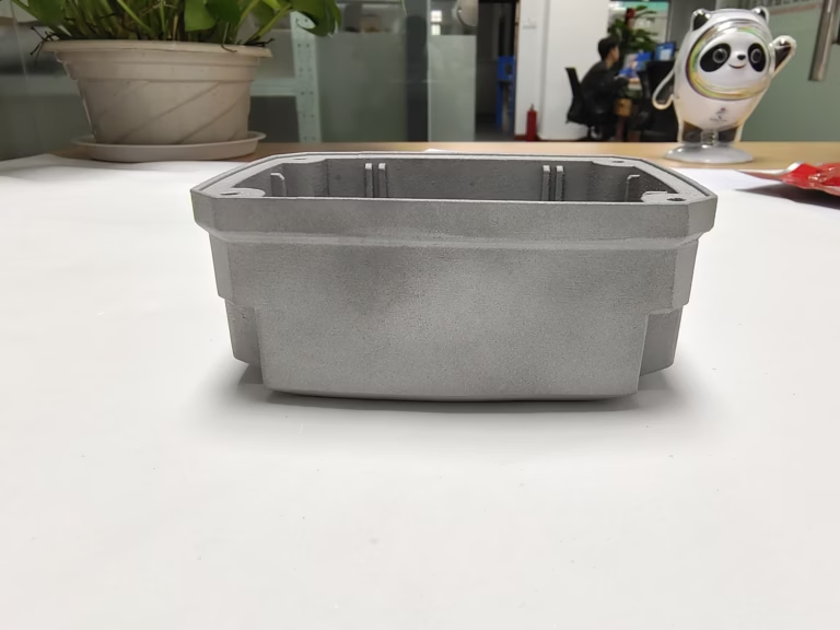
Pick the Tool That Matches the Geometry
The seven programs below are grouped by modeling method, not by price or brand popularity.
Parametric Tools for Functional Parts
Fusion 360 combines parametric modeling, direct modeling, mesh repair, CAM, and simulation under one subscription. For 3D printing the useful part is export control: you set chord height and angle before writing an STL, so a curved boss does not turn into a faceted lump. The same STEP file can be handed to a machine shop later without rebuilding the model. Teams that print brackets, enclosures, and fixtures usually start here.
SolidWorks remains the default in most mechanical design offices, and its STL export dialog is still the most granular of the three. You can drive deviation and angle tolerance separately, which matters on thin walls and lattice structures where a coarse mesh closes small gaps. Configurations let one file hold a printed prototype and a machined production version side by side. The trade-off is cost and a heavier install.
Onshape runs the same class of parametric kernel in a browser, with version control built into the document rather than bolted on. Branching and rollback work like a code repository, so a design review does not end with six copies of the same file. Export to STL or STEP is one click. Shops with several engineers on one part tend to like the shared history. Anyone offline will not.
Mesh and Freeform Tools for Organic Shapes
Blender is a mesh modeler, not a CAD system. It has no feature tree, no dimensions in the engineering sense, and no native STEP output. What it does have is sculpting, subdivision surfaces, and a huge add-on ecosystem. Use it for figurines, grips, cosmetic shells, and anything judged by silhouette rather than by a tolerance callout. Bring the result into a parametric tool before you cut mounting holes.
Rhino 7 sits between the two worlds. Its NURBS engine handles Class A surfaces and complex curvature, and Grasshopper lets you drive geometry from a parameter list. SubD tools cover the organic end without leaving the program. For 3D printing, the practical limit is watertightness: Rhino will happily let you build open surfaces, so run a mesh check before slicing. Jewelry, footwear, and ducting work well here.
FreeCAD is the open-source option and the one most often tested against paid seats. Part Design gives you a real history tree, and the Path workbench covers basic toolpath work. It is slower to learn than Tinkercad and less polished than Fusion 360. Version stability varies between releases. If your team cannot use cloud tools or licensed seats, it is a workable path for simple machined and printed parts.
Entry-Level and Browser Tools
Tinkercad is Autodesk's free browser app and it behaves like digital modeling clay. Drag solids, combine them, subtract them, export an STL. No sketch constraints, no drawings, no assemblies. It is a good fit for teaching, for quick concept blocks, and for a spacer or a cable clip that you need in twenty minutes. Do not try to hold a ±0.05 mm fit in it. The tool was never built for that.
The honest ranking question is not which program is best in general. It is which program fits the part in front of you. A printed impeller that will later be machined in aluminium needs a parametric history and a clean STEP file. A printed jig for a trade show needs a mesh and a slicer. Choosing the wrong side of that line costs more time than the license fee ever will.
Seven CAD Programs at a Glance
Modeling method and export format decide whether a file can move to production.
| Program | Modeling method | Best for | Export to production |
|---|---|---|---|
| Fusion 360 | Parametric + mesh | Functional prototypes, fixtures | STEP, STL |
| SolidWorks | Parametric | Production mechanical parts | STEP, STL, drawings |
| Onshape | Parametric, cloud | Distributed engineering teams | STEP, STL |
| Blender | Mesh, subdivision | Organic and sculpted shapes | STL only |
| Rhino 7 | NURBS + SubD | Curved surfaces, jewelry, ducting | STEP, STL |
| FreeCAD | Parametric, open source | Offline and license-free work | STEP, STL |
| Tinkercad | Primitive solids | Concepts, teaching, simple parts | STL only |
From Printed Prototype to Machined Part
A printed part proves geometry. It rarely proves strength. Layer direction, infill, and resin cure all change how a prototype behaves, so a passing fit test says little about a part under load. When the design is frozen, the usual next move is machining from aluminium or stainless, where the same STEP file drives the toolpath directly. Keeping the model parametric makes that handoff short.
Design rules shift at that point. Printed ribs can be thin and unsupported; a milled rib needs a cutter to reach it. Internal channels that print fine may need a drilled cross-hole instead. Radii should match a standard cutter, and deep pockets need clearance for the holder, not just the tool. Review the geometry against the machine before you commit to a print-to-mill transition.
We machine parts from the same CAD files engineers send for printing, on 127 CNC machines across three plants in Dongguan and Singapore. Tolerances reach ±0.005 mm and finishes reach Ra 0.2–0.8 μm when the drawing calls for it. Send a STEP file and we return a quotation and a DFM analysis within 12 hours, with production able to start within 24 hours. Uploads stay confidential and an NDA is available on request.
Questions Engineers Ask About CAD for 3D Printing
Can I send a CAD file straight from a 3D printing program for CNC machining?
Yes, if the program exports a solid format such as STEP. Mesh-only programs like Blender and Tinkercad export STL, which a CAM system can read but cannot use for dimensioned features.
A STEP file carries the surfaces and edges the toolpath needs. An STL carries triangles only, so a shop either rebuilds the model or works from the mesh with looser tolerance.
Which CAD program is best for parts that will be both printed and machined?
Any parametric tool with STEP export. Fusion 360, SolidWorks, Onshape, and FreeCAD all qualify.
The deciding factor is the history tree, not the print features. You want to change a wall thickness or a hole size later without rebuilding the part from scratch.
Does STL export resolution affect the printed part or the machined part?
It affects the printed part directly. A coarse chord height flattens curves, and slicers will reproduce those flat facets.
For machining it matters less because the shop works from STEP. If only an STL exists, a fine mesh helps the shop reconstruct the surfaces accurately.
Is free CAD software good enough for production parts?
FreeCAD can produce a valid STEP file for a straightforward part, and we have machined from files built in it.
The risk is version stability and surface quality on complex curvature. For a simple bracket or a plate, it is fine. For Class A surfaces, use a NURBS tool.
What tolerance can I expect on a machined part made from my 3D model?
We hold ±0.005 mm on critical dimensions when the drawing specifies it, and 100% inspection runs before shipment.
That is far tighter than any desktop printer. Keep the printed prototype for fit checks and put the real tolerance callouts on the machined drawing.
How do you protect the CAD files I upload?
Uploads are treated as confidential, and we sign an NDA on request before files change hands.
Our quality system is certified to ISO 9001:2015, IATF 16949:2016, ISO 13485:2016, and ISO 27001:2022, which covers information security.
Send the CAD File and Get a Machining Quote
Upload a STEP or STL file and our engineers return a quotation with free DFM analysis within 12 hours.
12-hour quote100% inspectionNo minimum order









