
3D Printing Troubleshooting: All SLA Issues and Solutions
This guide covers 3D printing troubleshooting all the way through the SLA workflow: exposure, supports, drainage, washing, and post-cure. It is written for engineers and buyers who need to judge whether a failed print is a setup problem or a process limit. Read it and you can pick the right fix, or decide the part belongs on a CNC instead.
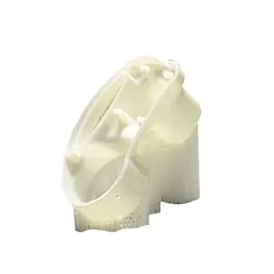
Read the failure, not the symptom
Most SLA failures trace back to one of five variables: exposure energy, support geometry, resin temperature, wash and cure, or part orientation.
Layer shift, blooming, and exposure errors
Layer shift on an SLA printer looks like a step in the Z direction, but it is rarely a mechanical fault. In most machines the cause is a loose build platform, a worn lead screw, or resin that has thickened at the bottom of the vat. Check platform runout with a dial indicator first. Anything over 0.05 mm of play means the platform needs re-torquing or replacement before you touch the exposure settings.
Blooming is the opposite problem. Overexposure pushes light into the previous layers, so edges grow wider as the part rises. You see rounded corners, lost holes, and a part that measures 0.15 mm oversize across a 20 mm feature. The fix is exposure. Run an exposure matrix, then reduce the normal layer time by 10–15% and the bottom layer time by 20%. Keep the bottom layers long enough for adhesion, usually 5–8 times the normal exposure.
Exposure also shifts with resin temperature. A vat at 20 °C needs more energy than the same resin at 28 °C. If your shop swings 8 °C between morning and afternoon, expect dimensional drift on tall parts. A heated vat or a temperature-controlled room removes this variable. For production parts, log vat temperature next to the exposure setting.
- 1Platform play over 0.05 mmRe-torque or replace the build platform before adjusting exposure.
- 2Blooming on cornersCut normal exposure 10–15%; check hole diameters with pin gauges.
- 3Cold resinBelow 22 °C, expect longer cure and higher dimensional drift on tall parts.
- 4Tall parts, one sideRotate the part so the tallest feature is not at the peel edge.
Warping, cupping, and support scars
Warping on SLA usually starts at the peel side. As the platform lifts, the cured layer sticks to the film and pulls the part. Thin flat panels bow; long brackets twist. Tilt the part 10–20° off the platform so each layer has less cross-section to peel. Add a raft only when the part is small and the footprint is narrow. A raft on a flat panel makes the warp worse by locking the first layers in place.
Cupping is a hollow section that traps resin and creates suction against the film. You hear a pop during the peel, and the part may delaminate near the closed end. Drain holes fix this. Put a 2 mm hole at the lowest point of every closed cavity, and a second hole at the highest point so air can enter. For a 30 mm cube with a hollow core, two holes are enough. For long channels, add a hole every 40 mm.
Support scars are a finishing problem, not a print failure, but they decide whether the part is usable. Contact tips that are too large leave pits on the surface. Tips that are too small let the part peel away. Use light tips (0.2–0.3 mm) on cosmetic faces and heavier tips (0.5–0.8 mm) on hidden faces and overhangs. If a face cannot carry any marks, orient it away from the supports or plan to machine it after printing.
- 1Flat panel warpsTilt 10–20° and drop the raft; reduce peel speed.
- 2Pop during peelAdd a 2 mm drain hole at the low point and a vent at the high point.
- 3Pits on a cosmetic faceUse 0.2–0.3 mm tips on that face; move heavy supports to hidden geometry.
Washing, post-cure, and dimensional drift
Under-washed parts stay tacky and grow a white film after cure. The film is uncured resin that has absorbed moisture. Wash in two stages: a dirty bath for 2–3 minutes to remove the bulk, then a clean bath for 1–2 minutes. IPA at room temperature works; warm IPA attacks some resins and softens fine features. If the part has thin walls under 1 mm, cut the first wash to 60 seconds and check.
Post-cure adds strength but also shrinks the part. A typical acrylic-like resin shrinks 0.4–0.8% during cure, and the shrink is not uniform. Thick sections shrink less than thin ones, so a 100 mm bracket can move 0.3–0.5 mm after 30 minutes under UV. Cure in short cycles and measure between them. For parts that must hold ±0.1 mm, cure first, then machine the critical faces.
Dimensional drift also comes from the printer itself. SLA holds ±0.1 mm on a well-tuned machine, but the error grows with part height. A 150 mm tall part may show 0.3 mm of Z error from peel forces alone. If your tolerance is tighter than ±0.1 mm, or the part has to fit a machined mating surface, SLA is the wrong process for the final part. Print it for form and fit, then cut the critical geometry on a CNC.
- 1White film after cureTwo-stage wash; keep IPA at room temperature.
- 2Shrink after UV0.4–0.8% typical; cure in short cycles and measure.
- 3Tolerance tighter than ±0.1 mmPrint for form, then machine critical faces on a CNC.
SLA failure, likely cause, and first fix
Use this table to narrow the cause before you change any settings. Change one variable at a time.
| Symptom | Likely cause | First fix |
|---|---|---|
| Layer shift (step in Z) | Platform play or loose lead screw | Check runout; re-torque platform |
| Blooming, oversize holes | Overexposure | Cut normal exposure 10–15% |
| Warped flat panel | Peel force at the film | Tilt 10–20°; remove raft |
| Pop or delamination | Cupping in a closed cavity | Add 2 mm drain and vent holes |
| Pits on cosmetic face | Support tips too large | Use 0.2–0.3 mm light tips |
| Tacky surface after cure | Under-washed part | Two-stage IPA wash, room temp |
| Part shrinks after UV | Post-cure shrinkage | Cure in short cycles; measure |
| Z error on tall parts | Peel force accumulates with height | Lower peel speed; reorient |
When SLA is the wrong tool
SLA is good at smooth surfaces, fine features, and small parts with organic geometry. It is a poor fit for load-bearing brackets, threaded holes, and any face that has to seal against another part. Cured resin creeps under sustained load, and a thread printed in resin strips at low torque. If a part carries a bolt, cut the thread after printing or switch the part to aluminum.
The break-even point is usually around 50 to 100 parts, or any part where two dimensions must hold tighter than ±0.1 mm. Below that, SLA and CNC both work, and the choice depends on geometry. A part with deep pockets, sharp internal corners, or a sealing face goes to CNC. A part with a smooth shell and no critical fits stays on SLA.
For functional prototypes, we often run both. Print the housing on SLA to check the feel and the cable routing, then machine the mounting plate and the connector interface on a 5-axis mill. The printed shell confirms the design; the machined parts confirm the fit. That split avoids a second round of tooling when the design changes.
GreatLight runs SLA for prototypes and CNC for production parts, with ±0.005 mm tolerance on machined features and Ra 0.8–1.6 μm as a standard finish. If a printed part fails the same way twice, send us the file and the failure photos. We will tell you whether the fix is in the print setup or in the process choice.
- 1Threaded holesResin threads strip; cut them on a CNC or use inserts.
- 2Sealing facesMove to machined aluminum; SLA surfaces leak.
- 3Sustained loadResin creeps; metal holds.
Common questions
How do I know if a failed SLA print is an exposure problem or a support problem?
Look at where the failure starts. Exposure problems show up across the whole part: rounded corners, oversize holes, and a soft surface. Support problems are local: one corner lifts, one overhang sags, or the part peels off the platform on one side.
Print a small test coupon with the same resin and orientation. If the coupon fails the same way, the setting is wrong. If it prints clean, the support layout on the real part is too light.
Why does my part measure correctly on the printer but shrink after post-cure?
Post-cure drives the resin to full conversion, and the part shrinks as the polymer network tightens. Typical shrinkage is 0.4–0.8%, and thin walls shrink more than thick ones.
Measure the part before and after cure to get the actual number for your resin. If the final tolerance matters, cure first and machine the critical faces afterward.
What causes a white film on the surface after washing and curing?
The film is uncured resin that stayed on the surface and then absorbed moisture during cure. It usually means the wash was too short or the IPA was already saturated.
Switch to a two-stage wash: dirty bath first to remove the bulk, clean bath second for the surface. Keep the IPA at room temperature. Warm IPA can soften thin features.
Can I print a part with a thread and use it as a functional fastener?
You can print a thread, but it will not hold the torque of a machined thread. Resin threads strip at low load, and the pitch is usually too coarse for a small screw.
Print the part with a pilot hole, then cut the thread on a CNC or install a metal insert. That gives you a joint that survives repeated assembly.
When should I stop troubleshooting and switch the part to CNC?
Switch when two dimensions must hold tighter than ±0.1 mm, when the part carries a load, or when it has a sealing face. Also switch if the same failure returns after you have corrected exposure, orientation, and supports.
SLA is fast for form and fit. CNC is the right process when the part has to work.
Does part orientation affect the final dimension on a tall part?
Yes. Peel force accumulates as the part grows, so the top of a 150 mm part can sit 0.3 mm off in Z even on a well-tuned machine. Orientation changes how much cross-section each layer has to peel.
Keep the tallest feature away from the peel edge, and lower the peel speed if the part is over 100 mm tall. For tight Z tolerance, machine the top face after printing.
Send the file and the failure photos
We will tell you whether the fix is in the print setup or in the process choice. Uploads are secure and confidential; NDA available on request.
12-hour quote and free DFM±0.005 mm tolerance100% inspection before shipment









