
3D Printing Technology Copper Casting: How the Detail Survives
A process-level walkthrough of how 3D printing technology copper casting workflows replace hand-carved wax, what the burnout cycle does to the shell, and which copper parts still belong on a CNC. Written for design engineers and foundry buyers.
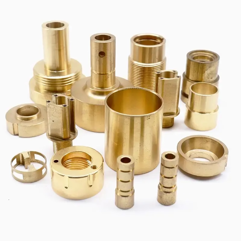
What 3D Printing Technology Copper Casting Actually Changes
Traditional lost-wax copper casting starts with a master pattern. Someone carves or machines it, then a rubber mold is cut, then wax is injected into that mold. Every design revision means a new tool. A 3D printing technology copper casting workflow deletes the rubber mold step entirely. The pattern is printed directly, invested in ceramic shell, and burned out.
The metal itself does not change. Copper pours at roughly 1,085 °C, and the ceramic shell sees the same thermal shock it always did. What changes is how the pattern was made, and how much geometry you can put into it before the pattern has to come out.
That last point matters more than the printing. A printed pattern can be hollow, latticed, or split into interlocking pieces. Features that a carved wax pattern could never release from a two-part rubber mold become buildable. Undercuts, internal channels, and 0.5 mm wall sections stop being tooling problems and become print parameters.
The trade is accuracy, not shape freedom. Printed patterns carry layer lines and resin shrinkage. Copper shrinks again when it solidifies. Both effects stack, and both land on the same part. That is why a printed-and-cast copper part rarely holds tighter than ±0.15 mm without a secondary machining pass.
- 1RemovedRubber mold and wax injection tooling
- 2AddedPrinted pattern, burnout cycle, ceramic shell
- 3UnchangedCopper alloy, pour temperature, shell chemistry
- 4Still neededCNC finishing for tight tolerances
Where the Dimensional Error Comes From
Error enters the process in four places. The printed pattern shrinks as it cures, typically 0.5–1.5 percent depending on resin. The ceramic shell expands when it is fired and contracts when it cools. Liquid copper shrinks about 2 percent on solidification, and thick sections shrink less than thin ones because they cool slower.
The last one is the hard one. Differential shrinkage is not a single number you can scale out of the model. A part with a 12 mm boss next to a 2 mm rib will pull in two directions. Printed patterns make this worse than wax in one way: you can now design wall thickness variations that a wax injection mold would never have allowed.
Foundries compensate with shrink factors applied to the print file, usually 1.5–2.5 percent uniform. That works for a simple bracket. It does not work for a thin-walled housing with a thick mounting pad. For those, plan a machining allowance of 0.3–0.5 mm on every face that matters.
Shell thickness is the other lever. A 6–8 mm ceramic shell holds up to the pour pressure of copper better than a thin one, but a thicker shell also grips the pattern harder during expansion. Thin, delicate copper castings often do better with a 5–6 mm shell built in more coats.
When Copper Casting Stops and CNC Starts
Copper casting earns its place when the geometry is complex, the volume is moderate, or the alloy is hard to cut. A manifold with internal flow channels, a heat sink with a dense fin field, a decorative fitting with deep relief: all of these are cheaper cast than milled.
It loses its place when tolerances tighten past roughly ±0.1 mm, when the part is thin and flat, or when the material is one of the free-machining copper grades. C101, C110 and C36000 cut beautifully. A 5-axis machine holds ±0.005 mm on them all day, with Ra 0.8–1.6 μm from the cutter and Ra 0.2–0.8 μm after polishing.
There is a middle path that often wins. Cast the rough shape with a printed pattern, then machine only the critical features. You get the casting's shape freedom and the machine's accuracy on the two or three surfaces that actually seal, slide, or bolt down. The casting tolerance in the non-critical zones stops mattering.
{'b': 'Cost check first', 'p': 'Below roughly 50 parts per year, printed pattern plus casting rarely beats CNC from bar stock.'}
{'b': 'Alloy check second', 'p': 'Beryllium copper and C36000 machine fast; cast versions are often porous.'}
{'b': 'Tolerance check third', 'p': 'Anything under ±0.1 mm needs a machining pass, cast or not.'}
Casting vs CNC vs Cast-Then-Machine
Pick the route before you pick the alloy.
| Route | Best for | Tolerance held | Typical wall | Watch out for |
|---|---|---|---|---|
| Printed pattern + casting | Complex internal geometry, 20–2,000 parts | ±0.15 mm as-cast | 1.5 mm and up | Differential shrinkage |
| CNC from bar stock | Tight fits, flatness, sealing faces | ±0.005 mm | 0.5 mm and up | Tool reach in deep pockets |
| Cast then CNC finish | Shape freedom plus tight critical faces | ±0.005 mm on machined faces | 1.5 mm cast, 0.8 mm cut | Extra setup, added lead time |
| Casting only, no print | Simple parts, existing wax tooling | ±0.20 mm as-cast | 2.0 mm and up | Tooling cost per revision |
The Short Answer
If the part has internal channels or relief you cannot mill, print the pattern and cast it, then machine the two or three faces that seal. If it is flat, thin, or needs ±0.005 mm across the whole part, skip the foundry and cut it from C101 or C36000 bar.
Questions Engineers Ask Next
Can a printed pattern survive the copper pour?
The pattern does not survive. It burns out of the ceramic shell during firing, usually between 600 °C and 800 °C, well before copper is poured at roughly 1,085 °C. What matters is that the pattern burns out cleanly and leaves no ash residue inside the cavity.
Standard castable resins burn clean. Some engineering resins do not, and they leave a carbon film that shows up as surface porosity on the casting. If your print shop uses a resin you have not cast before, ask for a burnout test on one pattern first.
How much machining allowance should I add?
On faces that will be machined, allow 0.3–0.5 mm per side. Below 0.3 mm you risk the cutter skating over a hard cast skin instead of cutting under it. Above 0.5 mm you waste material and cut time, and on thin sections you may bow the part.
On faces that stay as-cast, add nothing but plan for ±0.15 mm. If the drawing says ±0.1 mm on an as-cast face, that face will need machining.
Does 3D printing technology copper casting work for beryllium copper?
Yes, but the case is weaker than for pure copper. Beryllium copper is used for its spring properties, and those depend on a solution-treat and age-hardening cycle. Cast beryllium copper often has enough porosity to scatter the hardness readings.
For a spring contact or a flexure, machine it from wrought beryllium copper bar instead. The wrought material has consistent grain direction and hardens predictably. Casting makes sense only when the shape cannot be cut.
What surface finish comes off a cast copper part?
As-cast copper comes out at roughly Ra 3.2–6.3 μm, with a slightly matte skin that varies by shell face. That is fine for a decorative fitting or a housing that gets powder coated.
If you need Ra 0.8–1.6 μm, plan a machining or polishing pass. Bead blasting gets you a uniform matte at low cost. Polishing reaches Ra 0.2–0.8 μm but is hand work, so it prices by surface area.
How many parts before printed patterns beat machined ones?
Below about 50 parts per year, CNC from bar stock almost always wins on total cost, because there is no pattern, no shell, and no finishing setup. Between 50 and roughly 2,000 parts, printed patterns plus casting usually wins if the geometry is complex.
Above that, dedicated wax tooling starts to pay off, and the printed pattern becomes a bridge to production rather than the production method itself.
Can you machine copper castings after they come out?
Yes, and this is the route we recommend for most functional copper parts. Cast the near-net shape, then hold it in a fixture and cut the sealing faces, bores, and bolt patterns on a 3-axis or 5-axis machine.
Copper cuts clean but it is gummy. Sharp tooling, high rake angles, and coolant help. We run C101 and C36000 at ±0.005 mm on machined faces, with Ra 0.8–1.6 μm off the cutter.
Send the Drawing, Get the Route
Upload a STEP file and we will tell you whether the part should be cast with a printed pattern, cut from bar, or cast and then machined, with a quote and DFM notes in 12 hours.
12-hour quote and DFMNo minimum order quantity100% inspection before shipment
More Process Notes
We publish setup notes, tooling trials and inspection data from the factory floor.











