
2025 3D Printing Technology Direction: What Changes on the Shop Floor
This page reads the 2025 3D printing technology direction from a machining point of view. It is written for design engineers and sourcing engineers who must pick a process, not a headline. After reading it you can tell which printed parts are worth quoting now and which belong on a mill.
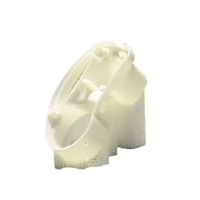
How to read the 2025 3D printing technology direction
Six shifts matter for part decisions. The rest is press release.
Materials move first, and that is what actually matters
Every serious shift in the 3D printing technology direction starts with the feedstock, not the machine. A printer that can run a new alloy is only interesting once that alloy has a data sheet, a repeatable heat treat, and someone who will certify it. In 2025 the useful movement is in engineering polymers and in a narrow band of metals. PEEK, PEKK and carbon-filled PA now print with mechanical values close enough to machined plastic that engineers will accept them for brackets and housings. That is a real change.
On the metal side, the printable list is still short compared with what a CNC shop stocks. Aluminium 6061 and 7075, 316L stainless, Ti-6Al-4V, Inconel and a few tool steels cover most of it. If your part needs 17-4PH in a specific condition, or 440C for wear, printing may not be the answer yet. Check the certification path before you check the geometry.
The practical question is not which material is newest. It is whether the printed version of that material behaves the same in your application. Fatigue, creep and galvanic contact with a mating metal part all behave differently in a printed lattice than in a solid billet.
- 1Good fitPEEK and carbon-filled PA for brackets, ducts, jigs and low-load housings
- 2Watch closelyTi-6Al-4V and 316L where the load path is simple and the wall is thick
- 3Hold backWear surfaces, sealing faces and anything needing a certified heat lot
AI, simulation and the closed loop
The second thread in the 2025 3D printing technology direction is process control. Machine builders now ship in-situ monitoring as standard on mid-range metal systems: melt pool cameras, layer imaging, and software that flags a suspect layer while the build is running. That is useful, but it is not the same as a digital twin that predicts distortion before the first layer. Most shops use simulation to place supports and pre-deform the model. Fewer use it to close the loop back into the slicer.
For a buyer the effect is simple. Fewer builds fail, and the ones that fail are caught earlier. It does not remove the need for post-build inspection. A printed part still goes on a CMM, still gets its critical dimensions checked, and still gets a material certificate tied to the powder lot.
Adaptive toolpaths matter more than the marketing suggests. When the slicer varies layer thickness or infill density inside one part, the thin section and the thick section cool at different rates. That is where residual stress lives. A good build plan accounts for it. A bad one prints fast and warps on the plate.
Printed part vs machined part: quick decision table
Use this when the drawing is ambiguous about process.
| Feature | 3D printing | CNC machining |
|---|---|---|
| Tolerance | ±0.1 mm typical, tighter on small parts | ±0.005 mm achievable |
| Wall thickness | 0.4 mm and up, depends on process | 0.5 mm and up, depends on tool access |
| Internal channels | Complex, conformal, no straight-line limit | Straight drilled or milled paths only |
| Material range | Narrow, certified list is short | Wide, hundreds of alloys and plastics |
| Surface finish | Ra 6–15 μm as built, needs post-work | Ra 0.8–1.6 μm off the machine |
| Unit cost at 1 pc | Low, no tooling | Higher, setup dominates |
| Unit cost at 10,000 pc | Mid to high, machine time bound | Low once fixturing is amortized |
| Best use | Prototypes, lattices, low volume | Production parts, tight fits, wear surfaces |
Speed claims and where they stop being true
High-speed resin and binder jet systems did get faster. Some polymer platforms now print a build every few hours rather than every day. That closes part of the gap with injection molding for runs in the low hundreds. It does not close the gap at ten thousand parts, and the material properties of a fast-cured resin are not the properties of a molded engineering plastic.
The honest position for 2025 is that printing and machining sit on the same bench, and both get quoted. We run both. A customer sends a housing with a complex internal channel and a tight bore. We print the channel geometry and machine the bore, or we split the part, print the shell and press in a machined bushing. That hybrid approach is where most of the real savings come from.
Anyone selling 3D printing as a replacement for machining is selling a story. Anyone selling machining as a replacement for printing is selling the same story from the other side. The bill of materials decides.
What to inspect on a printed part
Inspection is where a lot of printed parts quietly fail. The outside dimensions can be perfect while the internal density sits at 96 percent instead of 99.9 percent. That void does not show on a caliper. It shows on a CT scan or a destructive cut. For functional parts we ask what the density spec is and how the supplier proves it.
Dimensional inspection follows the same logic as machining. Identify the critical-to-function dimensions, put them on a first article report, and check them again on the final part. For printed metal we also want the powder lot number, the build orientation, and the heat treat record. Without those three, a material certificate is just a piece of paper.
Post-processing is part of the spec, not an afterthought. Support removal, stress relief, HIP, machining of mating faces and surface finishing all change the final part. If the drawing does not call them out, the supplier will pick the cheapest option.
Common questions from engineers
Can 3D printing hold the same tolerance as CNC machining?
Not on a general basis. Printed metal parts typically land around ±0.1 mm, and polymer parts vary more because of shrinkage and warpage.
CNC machining reaches ±0.005 mm on the same geometry when the part is rigid enough and the setup is right. If a drawing has a press fit or a sealing face, machine it.
Which is cheaper for a run of 50 parts?
It depends on geometry and material, not on the count alone. A complex lattice bracket at 50 pieces usually prints cheaper because there is no fixturing.
A simple prismatic block at 50 pieces machines cheaper because the cycle time is short. Ask for both quotes before you commit.
Do printed parts need post-machining?
Often yes. Interfaces, bores, threads and sealing surfaces usually need a cut to reach the drawing tolerance.
We plan the print with machining stock on those faces so the second operation is a light pass, not a full re-cut.
What materials can be printed and then machined?
Aluminium, stainless steel, titanium and tool steels are the common printed metals that machine well afterward.
Among polymers, PEEK, PA and PC print and machine acceptably. Filled materials wear tools faster, so plan for that.
How do you keep a design confidential?
Uploads are handled as confidential, and we sign an NDA on request before files move.
Only the engineers who need the files for quoting and programming see them.
How fast can a printed or machined part ship?
Quotation and a DFM review come back within 12 hours for most files, and production can start within 24 hours.
Parts normally ship in 3–5 days depending on process, finishing and quantity.
Send the drawing and we will tell you which process fits
Upload a STEP file and we return a quote with a manufacturability review, and we will say plainly if printing is the wrong choice for your part.
Quote within 12 hours100% inspection before shipmentNDA on request









