
3D printing makes rapid prototyping easy
This page explains where additive manufacturing fits in a prototype build and where it stops being the right tool. It is written for design engineers and sourcing teams who need to choose a process before the first drawing is released. Read it and you can judge whether a part should be printed, machined, or split between the two.
What this page covers
A process-level look at 3D printing for prototypes, plus the point where a printed part stops answering the question you are asking.
How a printed prototype is built, layer by layer
Additive manufacturing builds a part by adding material rather than removing it. The file is sliced into layers, and each pass deposits or cures a thin cross-section until the geometry closes. Layer height sets the trade-off: 0.1 mm gives smoother walls, 0.2 mm prints faster. Support structures hold overhangs and are cut away afterward.
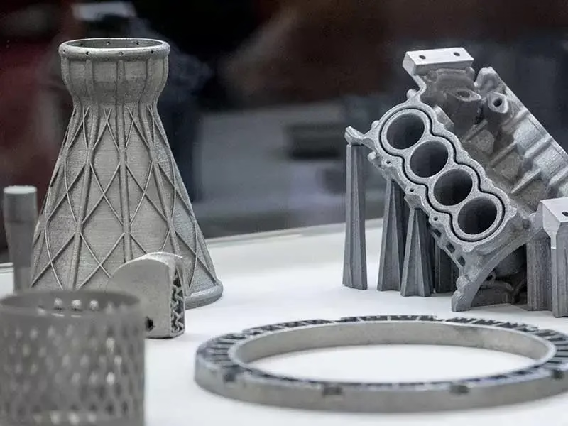
Three processes cover most prototype work. FDM extrudes thermoplastic filament and is the cheapest route to a bracket or housing. SLA and DLP cure resin in a vat, which suits fine features and smooth surfaces. SLS and MJF sinter nylon powder without supports, so undercuts and internal channels come out clean.
The workflow has four steps. Export a watertight STL or STEP file, orient the part for strength and surface quality, print and remove supports, then post-process. Post-processing is where a rough green part becomes something you can hand to a customer: sanding, bead blasting, dyeing, or painting.
Print orientation matters more than most people expect. A cylinder printed upright shows layer lines on the curved wall; printed on its side, the same cylinder is smoother but weaker across the layers. Decide which property the test is measuring before you hit print.
- 1FDMThermoplastic filament, low cost, visible layer lines
- 2SLA / DLPResin, fine detail, smooth surface, brittle unless cured well
- 3SLS / MJFNylon powder, no supports, good for snap-fits and ducts
- 4DMLSMetal powder, functional metal parts, higher cost per part
Picking a material for the question you are testing
The printed material should match the failure mode you care about. A fit check only needs dimensional accuracy, so PLA or standard resin is enough. A drop test or a loaded hinge needs toughness, which points to ABS, PC, or nylon. A heat test above 100 °C rules out most resins and most PLA.
Nylon (PA12) is the usual choice when a prototype has to survive assembly and field handling. It takes threads, living hinges, and repeated snap cycles reasonably well. PEEK and PEI are available when temperature or chemical resistance is the constraint, but expect a much higher part cost and a narrower supplier base.
Resins vary widely. Standard resin is stiff and brittle. Tough resins flex before they break. High-temperature resins hold shape to around 150 °C. If a resin part will sit in sunlight or under load for weeks, check the datasheet for creep and UV behavior instead of assuming it behaves like molded plastic.
Color and finish are secondary for a functional prototype but matter for a presentation model. Dyeing, painting, and bead blasting all work on printed parts. Keep in mind that sanding a resin surface can round edges that were dimensionally critical, so mask those areas first.
- 1Fit check onlyPLA, standard resin, cheapest and fastest
- 2Loaded or handled partABS, PC, PA12 nylon
- 3Heat above 100 °CPEEK, PEI, high-temp resin
- 4Metal prototypeDMLS in aluminium or stainless, then machine critical faces
Printing versus CNC for a prototype
Both routes are valid. The choice depends on what the next test measures.
| Factor | 3D printing | CNC machining |
|---|---|---|
| Typical tolerance | ±0.1 to ±0.3 mm | ±0.005 mm |
| Surface finish | Ra 3.2–12 μm as printed | Ra 0.8–1.6 μm standard |
| Material range | Thermoplastics, resins, some metals | Aluminium, steel, stainless, titanium, plastics |
| Best for | Complex geometry, internal channels | Tight fits, threads, functional testing |
| Setup cost | None, file to part | None for 1-off, programs reused later |
| When it stops working | Load-bearing fits, sealing faces | Deep internal channels, hollow shells |
| Lead time | Often 1–3 days | 3–5 days after drawing release |
Where a printed part stops being useful
Layer lines create anisotropic strength. A printed part is weaker between layers than along them, sometimes by 30 to 50 percent depending on process and orientation. If the prototype will see the same load direction as the final part, that weakness can hide a real design problem or create a false one.
Tolerances are the second limit. A printed bore will not hold a press fit or a bearing seat. If the test is whether a shaft enters a housing, print the housing and machine the bore. Mixing processes on one assembly is normal and often cheaper than pushing either process past its range.
Sealing faces, O-ring grooves, and threaded joints rarely work as printed. The surface texture leaks, and the thread profile is too coarse. Tap the printed hole for a light-duty thread, or design an insert. For anything holding pressure, machine the sealing face.
Fatigue is the quiet problem. A resin or FDM part may pass the first 100 cycles and crack at 1,000. If the prototype is going into a cycle test, use a machined metal part for the loaded member and print only the non-structural shell.
Cost also flips at volume. Printing one part is cheap. Printing 200 identical parts is not, once you count machine time and manual finishing. Between roughly 50 and 200 units, machining or vacuum casting usually wins on unit cost and repeatability.
Running a print-then-machine prototype build
The most reliable prototype strategy uses both processes in sequence. Print the geometry to check form, fit, and assembly order. Once the shape is settled, machine the critical interfaces to final tolerance. The printed part answers shape questions; the machined part answers function questions.
At GreatLight we run this as a single job. Send a STEP file and we return a DFM analysis within 12 hours, flagging features that should be printed and features that should be machined. Production can start within 24 hours, and parts ship in 3 to 5 days. There is no minimum order quantity, so one prototype and a 10,000-part run go through the same process.
Our shop holds 127 high-precision CNC machines, including 16 simultaneous 5-axis centers and a Ø400 mm rotary table. Maximum processing size reaches 4,000 mm, so printed concept models can be paired with machined frames, plates, and housings in the same assembly.
Inspection is 100 percent before shipment, with raw material checks, in-process monitoring, and final reports on request. Tolerances hold to ±0.005 mm (±0.0002 in) on machined features, and finishes run from Ra 1.6–3.2 μm as-machined down to Ra 0.2–0.8 μm when a sealing surface needs it.
Uploads stay confidential and an NDA is available on request. That matters when the prototype is unreleased hardware and the file carries more information than the part itself.
Common questions
Can I print a prototype and then machine the same design?
Yes, and it is a common path. The printed part confirms shape and assembly, then the machined version confirms fit, load, and sealing. Keep one master CAD model and derive both.
If the printed geometry already matches the final design, the machined part needs no redesign. Only the tolerance callouts change.
What file format do you need for a quote?
STEP is preferred because it carries exact geometry and is easy to tool-path. STL works for printing but loses feature names and dimensions.
Send the drawing alongside the model. Tolerance callouts, material, and finish decide the process more than the shape does.
How tight can a printed prototype hold?
Expect ±0.1 to ±0.3 mm on most processes, with the tighter end on SLA and SLS. FDM drifts more on tall parts.
Anything that has to mate, seal, or spin needs machining. Print the surrounding form and machine the interface.
Is a printed prototype strong enough for a functional test?
For light handling, yes. For repeated load or cycle testing, no. Layer adhesion is the weak point and it fails progressively.
Use a machined metal part for the loaded member and print the non-structural parts around it.
At what quantity should I switch from printing to machining?
Around 50 to 200 identical parts, depending on geometry. Below that, printing is usually faster. Above it, machining or vacuum casting wins on unit cost.
The crossover moves with part size and finishing time. A small bracket with no finishing flips earlier than a large housing that needs sanding.
Do you sign an NDA before I send files?
Yes. An NDA is available on request and uploads are handled as confidential.
That covers both the CAD data and any test results you share with the quote request.
Send a prototype file and get a process recommendation
Upload a STEP file and we will return a DFM analysis within 12 hours, with a clear split between what to print and what to machine.
12-hour quoteNo minimum order quantity100% inspection before shipmentNDA on request









