
3D Printing Injection Molds: What Works and What Doesn't
This guide is for engineers deciding whether a printed mold can carry a pilot run before steel is cut. It covers resin and metal options, real cavity pressure limits, draft and gate rules, and the point where you should move to a machined tool.
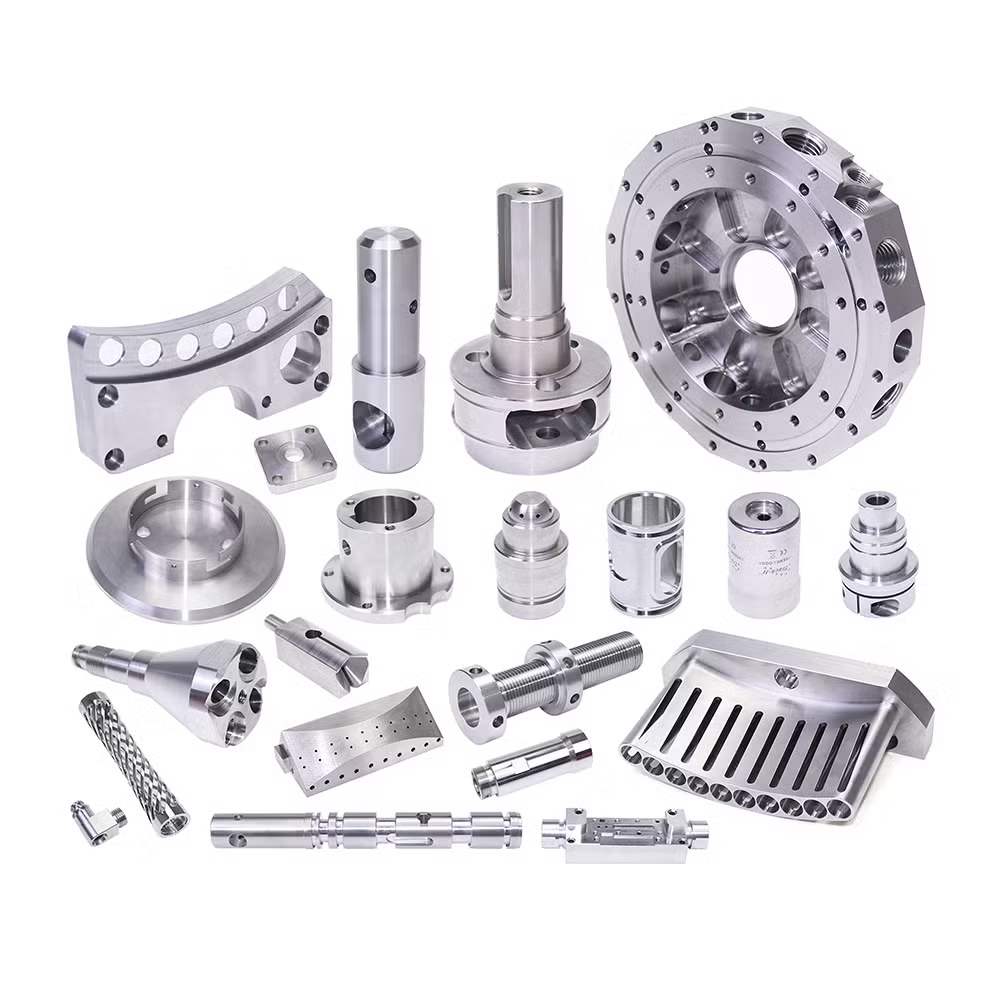
Printed tooling for injection molding
Two very different things share the name: a plastic mold printed for low-volume runs, and a metal insert printed and then machined to final size. They behave nothing alike.
The two routes and where each one breaks
A 3D printed injection mold is a tool that is additively built rather than cut from a billet. The distinction that matters on the shop floor is what the tool body is made of, because that sets the cavity pressure it can survive and the number of shots before it fails.
Route one is a polymer tool. Resin is printed, cured, and sometimes backed with a metal frame or epoxy. It runs on a standard press, but cavity pressure stays in the low range, roughly below 20 MPa, and you should plan for tens of shots rather than thousands.
Route two is a metal tool. An insert is printed from maraging steel, H13, or a bronze-copper alloy, then the parting faces, sprue, and any sealing surfaces are CNC finished. This route behaves much closer to a conventional tool and can reach thousands of shots when cooling and support are designed properly.
Neither route replaces a production steel mold. Both are ways to get real molded parts in your hands while the hard tool is still being quoted or cut.
- 1Polymer toolFastest and cheapest. Good for fit checks and a few dozen parts.
- 2Metal insert toolNeeds CNC finishing on sealing faces. Reaches higher shot counts.
- 3Conformal coolingThe main reason to print a mold at all. Curved channels follow the part contour.
- 4Production steelStill the right answer above roughly 10,000 shots or tight tolerance.
Cavity pressure, temperature, and shot count
Every printed tool decision comes back to three numbers: cavity pressure, melt temperature, and required shot count. Get these wrong and the tool fails in the press, sometimes on the first shot.
Resin tools handle unfilled PP, PE, and ABS at low pressure. Glass-filled nylon or PC at 300 °C will deform the cavity or crush the core. If your resin data sheet lists a high melt flow index and your part has a thick wall, the pressure spike at the gate is where the tool gives out.
Metal inserts tolerate filled materials and higher temperatures, but printed metal is porous and about 95 to 98 percent dense after sintering. Sealing faces must be machined, otherwise flash runs along the layer lines. We machine those faces to ±0.005 mm and Ra 0.8–1.6 μm so the tool closes cleanly.
Cooling changes the cycle, not the shot count. Conformal channels printed close to the cavity pull heat out faster and reduce warpage on thick sections. That is the one place where 3D printing injection molds clearly beat a drilled tool.
- 1Low pressure onlyKeep resin tooling under roughly 20 MPa cavity pressure.
- 2Filled resinsUse a metal insert. Glass and carbon fibres abrade polymer cavities.
- 3Shot countPlan tens of shots for resin, low thousands for metal inserts.
- 4Wall thicknessThick walls raise pressure and extend cooling. Both hurt tool life.
Tool material comparison
Pick the tool body by material, volume, and tolerance, not by printer availability.
| Tool type | Typical shots | Best for | Main limit |
|---|---|---|---|
| Printed resin | 10–100 | Fit and form checks | Low cavity pressure |
| Resin with metal frame | 100–500 | Pilot runs in PP or ABS | Flash at parting line |
| Printed metal insert | 1,000–10,000 | Filled resins, higher temp | Needs CNC sealing faces |
| Machined aluminium | 10,000–100,000 | Bridge and low-volume tools | Softer than steel |
| Machined steel | 100,000+ | Production, tight tolerance | Cost and lead time |
Design rules that keep a printed tool alive
The same rules that make a part moldable still apply, and printing does not relax them. Draft of 1–2° per side is the minimum for a printed cavity; below that the part drags and tears the tool surface. Add more draft on textured or printed walls.
Layer lines run across the cavity surface, so ejection forces are higher than in a polished steel tool. Place ejector pins under ribs and bosses, not on flat cosmetic faces. A small draft on every vertical wall does more for tool life than any post-process.
Gate location decides where the tool wears. Direct gates concentrate pressure on one spot and erode a printed surface quickly. A short runner with a fan or edge gate spreads the flow and takes longer to damage.
For printed metal, orient the insert so layer lines run parallel to the parting plane. That keeps the sealing face machinable and puts the weak direction out of the pressure path.
- 1Draft1–2° minimum per side. More on printed or textured walls.
- 2Uniform wallVary wall thickness by no more than 2:1 to avoid sinks and pressure spikes.
- 3FilletsRadius internal corners. Sharp corners crack under repeated cycling.
- 4EjectionPin under ribs and bosses. Avoid pin marks on cosmetic surfaces.
When to stop printing and machine the tool
Printed tooling earns its place in the gap between a CAD model and a steel mold. It stops earning its place when the numbers move past the limits above.
Switch to a machined tool when the required shot count climbs into the thousands, when the resin is glass or carbon filled, when the part tolerance is tighter than ±0.05 mm, or when the cosmetic surface must be a specific gloss. Printed cavities carry layer texture into the part, and polishing it out is slow and unreliable.
For bridge production we machine aluminium tools on 5-axis centers, with 16 simultaneous 5-axis machines available and a maximum processing size of 4,000 mm. Those tools run tens of thousands of shots and can be cut in the same week the design freezes.
The practical sequence is simple. Print the tool, mold the parts, check fit and function, then commit to a machined tool once the design stops changing. That keeps tooling spend aligned with design maturity.
Common questions
Can a 3D printed mold run on a standard injection press?
Yes, with a steel frame or bolster to take the clamp force. The printed cavity sits inside that frame and only sees cavity pressure.
Keep clamp force low and watch the first shots for flash at the parting line. If flash appears, the tool is closing on a high spot, not sealing.
How many parts can I realistically get?
Plan tens of shots for a plain resin tool, a few hundred with a metal frame, and low thousands for a printed metal insert with machined sealing faces.
Filled resins and thick walls cut those numbers. Unfilled PP or PE at low pressure extends them.
Which material should I choose for a printed insert?
Maraging steel for wear resistance, H13 for hot work, and bronze-copper alloys when heat transfer matters more than strength.
The insert is printed near net shape, then the parting faces, sprue, and sealing surfaces are CNC finished to final tolerance. Print stock must be left on every face that seals.
Why machine the face of a printed metal insert?
Sintered metal is porous and slightly undersized. A printed sealing face leaks, and flash follows the layer lines.
Machining to ±0.005 mm with an Ra 0.8–1.6 μm finish closes the tool properly and gives the part a clean edge.
Does printing a mold reduce cost for low volume?
It removes the cost of a steel tool for the first few hundred parts. That is where the saving comes from.
Above a few thousand parts the printed tool wears and the cost per part rises. At that point a machined aluminium or steel tool is cheaper per part.
Can you help with tool design before printing?
Yes. Send the part model and we return a free DFM analysis covering draft, gate location, wall thickness, and parting line within 12 hours.
We can quote the printed tool and the machined tool side by side so you can compare them before committing.
Send your part model, get a tooling plan
We review draft, gates, and wall thickness, then quote the printed tool and the machined alternative in one response.
12-hour quote and DFM±0.005 mm machining100% inspection before shipmentNDA on request









