
3D Printer Extruder Body CNC Turning: A Process Guide
This page covers how a 3D printer extruder body is turned, which features need a lathe rather than a mill, and how material and tolerance choices affect print quality. It is written for design engineers and sourcing teams who need to read a drawing and judge whether a quote will hold up.
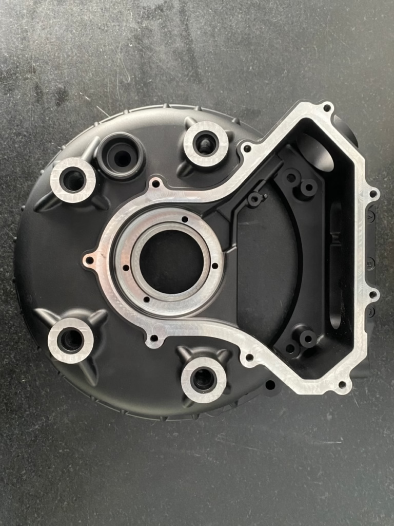
What a turned extruder body has to get right
A short orientation before the process detail.
The extruder body is a tolerance stack, not a housing
The extruder body holds four things in alignment: the filament path, the heat break, the heater and thermistor, and the nozzle. On a direct-drive FFF head, those parts sit within a few tens of millimeters of each other, so every error in the body adds to the error in the assembly. A bore that drifts 0.01 mm off center shifts the melt zone. A face that is not square to the bore axis tilts the nozzle and changes the gap at the first layer.
Turning suits this part because most of its critical features share one axis. The filament bore, the heat break counterbore, and the nozzle thread all run along the same centerline, which is exactly what a lathe holds well. A mill has to interpolate that centerline from several directions. A lathe turns it in one continuous cut.
That single-axis geometry also makes inspection simple. A bore gauge and a micrometer on the shoulder tell you most of what you need to know. The features that do not share the axis, such as the mounting bolt pattern and the fan bracket, are usually secondary and rarely carry the same tolerance.
Which features belong on the lathe and which do not
Start the split by asking which features control the filament path. Bores, counterbores, nozzle threads, and the shoulder the heat break seats against all belong on the lathe. They are round, they are concentric, and their fit to the heat break determines how much heat creeps up the filament. A heat break that seats 0.05 mm high changes where the transition zone sits.
Flat features belong on a mill. A mounting flange with four bolt holes, a fan shroud cutout, or a slot for a wire clip needs an interpolated path, not a turning tool. Doing those on a lathe with a live tool works for light cuts, but deep pockets and tight corner radii still favor a mill.
For a body that needs both, a turn-mill center keeps the part on one spindle between operations. That matters for concentricity. Remove the part, re-chuck it in a second machine, and you reintroduce the error you just spent time removing. We run 16 mill-turn centers for exactly this kind of part.
Material choice for a turned extruder body
Match the alloy to the temperature at the heat break, not to the whole printer.
| Material | Best for | Watch out for |
|---|---|---|
| 6061-T6 aluminum | Direct-drive heads up to about 250 °C | Softens above 200 °C, threads wear |
| 7075 aluminum | Stiff lightweight gantries | Poor corrosion resistance, costs more |
| 303 stainless | Threaded bores that see rework | Not for high-temp melt zones |
| 316L stainless | Corrosive filament, long service | Heavier, slower to cut |
| Ti-6Al-4V | High-temp and lightweight heads | Tool wear, cost, long cycle time |
| PEEK | Insulating body sections | Machining needs sharp tooling, no coolant soak |
Tolerances that actually change print quality
Not every dimension on an extruder body needs ±0.005 mm. Spending tolerance where it does nothing raises cost and narrows the supplier list. The filament bore and the heat break counterbore are the two that pay off. Hold those tight and the rest of the part can sit at ±0.05 mm without anyone noticing.
The nozzle thread is a fit, not a precision diameter. A 6 mm thread cut to the right pitch class seats without galling, and that is the whole requirement. Over-tightening a thread to fix a leak is a symptom of a bad shoulder face, not a bad thread.
Surface finish in the filament path is a separate lever. A bore at Ra 0.8–1.6 μm feeds filament with low drag. Polishing below that helps only marginally and can round the bore edge, which then catches the filament tip on loading. For most builds, Ra 0.8–1.6 μm is the right target and Ra 0.2–0.8 μm is reserved for abrasive filament.
Setup, workholding, and how the quote is built
An extruder body is small and often thin-walled, so workholding drives the process plan more than the cutting does. A part with a 1.5 mm wall will deflect if the chuck jaws close on it with too much force. The usual answer is to leave a stock boss for the jaws and remove it in a second operation, or to turn between centers when the geometry allows.
For one-off prototypes, a three-axis lathe with a bar feeder is enough and keeps the price low. Once the design is fixed and the quantities climb, a turn-mill center with a subspindle cuts the part complete in one cycle. That is where the per-part cost drops. Setup time is spread over more parts, and there is no second-op queue.
Both paths start the same way. Send a STEP file with the critical dimensions marked and we return a DFM note within 12 hours. That note usually flags two or three things: a wall too thin to hold, a thread that has no relief at the bottom, or a shoulder face that cannot be reached with a standard tool.
Cases where turning is the wrong answer
Complex internal cooling channels rule out turning as the primary process. A body with a conformal coolant path around the melt zone needs either additive manufacturing followed by finish machining, or a two-piece design that is brazed or bolted together. Turning can finish the mating faces, but it cannot create the channel.
Very low quantities of a complex body are another case. If you need three units of a part with six milled pockets and two bores, the setup cost per unit is high and the geometry may be easier to print and then ream the bores. We run custom 3D printing in the same plant, so the honest comparison is available.
Finally, a body that is mostly a machined plate with one bore does not need a lathe at all. A three-axis mill drills and reams that bore fine. Turning earns its place when round features dominate and concentricity is the controlling requirement.
Questions engineers ask before ordering
What tolerance can you hold on an extruder body bore?
We hold ±0.005 mm on turned diameters and bores under normal shop conditions.
That figure assumes the feature is reachable with a standard boring bar and the wall is thick enough to resist clamping force. Thin walls may need a relaxed tolerance or a different workholding plan.
Which file format should I send for a quote?
A STEP file plus a 2D drawing with the critical dimensions marked is the fastest combination.
If you only have an STL, send it and note which features matter. We will tell you what cannot be read from the mesh.
Can you turn the body and anodize it in one order?
Yes. Anodizing in clear, color, hardcoat, and conductive versions is available, along with bead blasting, brushing, and laser marking.
Note that hardcoat anodizing adds a hard oxide layer of roughly 20–50 μm per surface. If the filament bore is a close fit, mask it or leave stock for the coating.
How do you keep the heat break counterbore concentric to the nozzle thread?
We cut both in the same setup on a turn-mill center, so they share one spindle axis.
When the part must move between operations, we use a soft jaw or a collet that repeats from the same datum, then verify concentricity on the CMM before the run continues.
What is the smallest quantity you will run?
There is no minimum order quantity. We run from a single prototype up to 10,000+ part runs.
For one or two pieces, expect the price to be dominated by setup. That is normal and it is worth asking whether a printed version with reamed bores would serve the same test.
How is confidentiality handled?
Uploads are secure and confidential, and we sign an NDA on request before drawings are shared.
Our ISO 27001:2022 certification covers the information security side of that process.
Send a drawing and get a DFM note back
Upload your extruder body STEP file and we return a quote with manufacturability comments within 12 hours.
12-hour quote100% inspection±0.005 mmNDA on request









