
Which Software To Use With CNC Machine?
A shop does not run on one program. Choosing a software to use with cnc machine usually means four layers: CAD for geometry, CAM for toolpaths, control software on the machine, and inspection or metrology for sign-off. This page compares them by part type, tolerance, and file format so an engineer can pick a layer without buying the wrong seat.
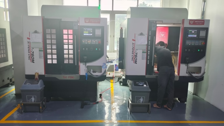
Which software layer does what
Match the layer to the job before you buy seats.
| Layer | Job it owns | Typical input | Fails when |
|---|---|---|---|
| CAD | Geometry, dimensions, tolerance callouts | Sketch, scan, customer model | Surface quality is not checked before handover |
| CAM | Toolpaths, feeds, speeds, stock removal | Solid model or surfaces | Tool holder and fixture are not modeled |
| Machine control | Motion, offsets, tool changes, probing | G-code from CAM | Post-processor does not match the control |
| Inspection | Measured values against the drawing | CMM or vision output | Tolerance stack is set after the first cut |
CAD: model quality decides everything downstream
CAD is where the part is defined. Sketches, features, datum callouts and tolerance notes all live here. If the model is sloppy, no CAM seat on earth will save the job. We see this most often on imported STEP files from industrial design packages, where a surface looks fine on screen but carries tangency breaks that show up as witness marks after anodizing.
Parametric modelers suit families of parts that evolve. Change a boss diameter and the drawing, hole pattern and CAM setup follow. Direct modelers suit one-off fixtures and repair work, where the geometry arrives as dumb solids and rebuilding a feature tree costs more than pushing faces around. Neither is universally better.
For machining work, the practical test is simpler: can the model carry GD&T that the CAM programmer and the inspector both read? A neutral STEP or IGES file with a clean solid and a separate PDF drawing beats a native file with no tolerance data every time.
GreatLight works from STEP, IGES, SLDPRT, X_T and native formats. We read the drawing tolerances and the model together before quoting, because ±0.005 mm on a thin wall is a different job than ±0.005 mm on a solid boss.
- 1Parametric CADBest for part families, revisions, and configurable assemblies.
- 2Direct CADBest for imported solids, fixtures, and quick repair geometry.
- 3Surface modelingNeeded for Class-A exteriors and blended fillets on housings.
CAM: toolpaths, stock, and the fixture you forgot to model
CAM turns the model into motion. It decides cut order, stepover, stepdown, lead-in, and whether a 3-axis job is really a 5-axis job. The common failure is not a bad toolpath. It is a good toolpath that ignores the vise, the clamps, or the tool holder shank.
Two questions sort most CAM packages for you. Do you need true simultaneous 5-axis, or is 3+2 positional enough? And does the package let you model stock and fixtures inside the same file? If the answer to the second is no, your programmer will rely on memory, and memory fails on the third setup.
Feeds and speeds libraries matter more than the splash screen suggests. A library tuned for aluminium 6061 will not help on Inconel or Ti-6Al-4V. Look for a package where you can store cutting data per material and per tool, then lock it so a junior programmer cannot quietly double the feed.
High-speed toolpaths with constant chip load are standard now. What separates packages is verification: stock removal simulation that catches a gouge before the spindle turns, and collision checking that includes the holder and the table.
- 13-axis CAMPrismatic parts, plates, and open pockets with one face per setup.
- 23+2 CAMAngled faces indexed on a trunnion or rotary table. Ø400 mm table on our mill-turn cells.
- 3Simultaneous 5-axis CAMImpellers, medical implants, contoured housings, undercut geometry.
Machine control and post-processors: where good code goes wrong
The control is the software already bolted to the machine. Fanuc, Siemens, Heidenhain, Mitsubishi and Haas all read G-code differently at the edges. A post-processor that emits the wrong canned cycle or the wrong tool change macro will scrap the first part, and sometimes the fixture too.
This is why a neutral post is a myth. The post must match the exact machine model, the control version, and how your shop sets work offsets. When we bring a new 5-axis center online, the post is validated on a test block before it touches customer material.
On-machine probing is part of this layer. Renishaw-style routines set work offsets and check features without pulling the part. For a first article, probing a datum and one critical bore can catch a setup error in two minutes instead of forty.
Keep the control software version documented per machine. A mid-run update that changes a macro or a look-ahead behavior is a real risk on long cycle jobs. We freeze versions during production runs and schedule updates between jobs.
- 1Post-processor validationCut a test block on the target machine before releasing the post to production.
- 2Work offset strategyAgree on G54 to G59 conventions with the programmer, not the operator.
- 3Version freezeDocument control software versions for every machine in the cell.
Inspection software: closing the loop on tolerance
Inspection software is the fourth layer and the one most often left out of the buying decision. A CMM or vision system produces numbers. The software decides whether those numbers map back to the drawing datums in the way the designer intended.
The classic error is a tolerance stack built after the first cut. If the drawing calls a position tolerance at MMC and the inspection program reports simple X-Y deviation, the report looks clean and means nothing. Datum reference frames must be defined once and used by CAM, the operator, and the inspector.
For production runs we compare measured values against the model and against the drawing, not just against each other. Trend data on a critical bore tells you when a tool is drifting, which is more useful than a pass or fail at final inspection.
If you receive a first article report, check the datum callouts before the numbers. A report with the wrong datum structure is worse than no report, because it looks authoritative.
- 1Datum reference frameOne definition shared by CAM, operator and inspector.
- 2First article reportAsk for measured values, not just pass or fail, on critical features.
- 3Trend dataBore and wall thickness trends flag tool wear before scrap.
So which software do you actually need?
If you are designing parts and handing them to a machine shop, you need CAD that produces a clean solid plus a tolerance drawing. If you are cutting the parts yourself, CAM and the post-processor decide your scrap rate, not the CAD brand. If you are buying machined parts, you do not need to buy any of it. Send STEP and a drawing, and ask the shop which layer they will run.
Common questions
Can I send a STEP file instead of native CAD?
Yes. STEP and IGES carry solid geometry and are enough to quote and machine most parts.
Include a PDF drawing with tolerances and datums. A model alone does not define what is critical.
Do I need 5-axis CAM for a 5-axis machine?
No. Many parts run as 3+2, where the table indexes to an angle and the cut is still three linear axes.
Simultaneous 5-axis CAM is worth the seat when the geometry is contoured, undercut, or needs one continuous pass.
Why does my post-processor produce alarms?
The post usually does not match the control version or the machine options installed.
Send the machine model and control type to the programmer. Post validation on a test block takes minutes and prevents a scrapped setup.
What file formats do you accept for quotation?
STEP, IGES, SLDPRT, X_T, and native formats, plus PDF or DXF drawings.
We review the model and drawing together and return DFM feedback within 12 hours.
Is my design data kept confidential?
Uploads are treated as confidential and an NDA is available on request.
We hold ISO 27001:2022 for information security management, alongside ISO 9001:2015, IATF 16949:2016 and ISO 13485:2016.
Can you machine from a scan or mesh file?
Sometimes. Mesh data needs to be converted to surfaces or solids before toolpath generation.
For reverse-engineered parts, expect a review step so we can confirm wall thickness and datum strategy.
Send the model and the drawing
Upload your CAD file and drawing. We return a quotation and free DFM analysis within 12 hours, with no minimum order quantity.
12-hour quoteNo minimum order quantity100% inspection before shipment
More from the shop floor
We publish setup notes, tooling trials and inspection data from the factory floor.











