
What Are the Trends in 3D Printing in 2024?
A process-level look at the shifts that actually changed shop floors in 2024, not the trade-show version. Written for engineers and buyers who need to decide whether a part belongs on a printer or a mill. By the end you can name the four or five movements that matter and say where each one breaks down.
In this article
- 1
- 2
- 3
- 4
- 5
- 6
- 7
Key takeaways
Trends in 3D printing in 2024: sinter-based metal went industrial
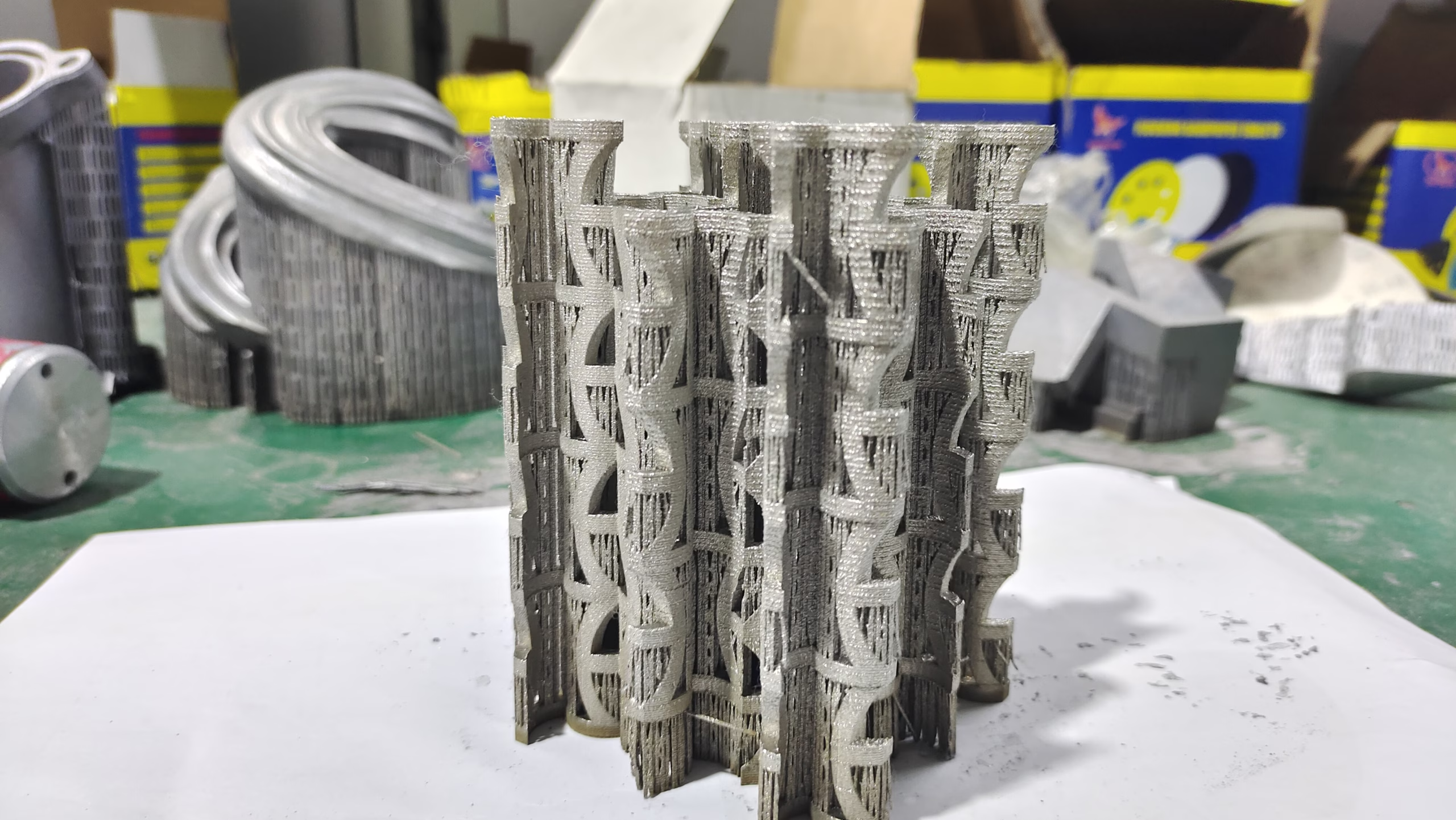
The loudest shift in metal was not a new laser. It was the maturing of sinter-based routes, mainly binder jetting and metal extrusion. Both print a green part held together by polymer, then debind and sinter it in a furnace. The furnace, not the printer, sets the final density and the tolerance stack.
Why this matters on a shop floor: binder jetting runs a full build box in one pass with a printhead, not a single laser spot. A build can hold hundreds of small parts nested tightly. That changes the economics for brackets, housings and small manifolds where you would otherwise run a casting tool or a long mill cycle.
The catch is shrinkage. Sintering pulls the part by roughly 15 to 20 percent in linear terms, so the printer scales the model up and the furnace must hold a tight profile. Distortion shows up on long, thin sections and on parts with uneven wall thickness. If your design has a 0.8 mm wall next to a 6 mm boss, expect to iterate.
Post-sinter tolerance typically lands around ±0.3 to ±0.5 percent of the dimension, which is far looser than the ±0.005 mm we hold on a 5-axis mill. For a 50 mm feature that is roughly ±0.15 to ±0.25 mm. Plan a finishing pass on any mating surface. Printing a near-net blank and machining the critical faces is the practical pattern we see most.
- 1Best fitSmall to medium metal parts, batch sizes in the hundreds, complex internal channels.
- 2Poor fitTight-tolerance bores, thin long parts, one-off pieces where a mill is faster.
Pellet extrusion and large-format polymer printing
On the polymer side the move was toward pellets instead of filament. A pellet-fed extruder uses the same resin beads that injection molders buy, so feedstock cost per kilogram drops sharply compared with spooled filament. Nozzles run from about 1 mm up to 6 mm, and a 2 mm nozzle lays down material several times faster than a 0.4 mm filament nozzle.
The trade is resolution. A 2 mm bead gives you a visible layer line and a rough surface, often Ra 12 μm or coarser before finishing. That is fine for a fixture, a jig, a duct or a large enclosure where the surface never touches a datum. It is not fine for a snap-fit housing with a 0.3 mm rib.
Large-format machines now print parts well over 1,000 mm in one piece, which changes how you think about assembly. A welded sheet metal frame that needed six panels and a fixture can become one printed shell. Fewer joints, fewer fasteners, but a much longer single print that ties up the machine.
Fiber reinforcement is the other half of this trend. Short carbon fiber and glass fiber pellets raise stiffness and cut thermal expansion. Printed with a 2 mm nozzle and 30 percent fiber by weight, a part can approach the stiffness of a glass-filled molded part in the print direction. Across the layer lines it is weaker, typically by a factor of two or more. Orient the load paths accordingly.
- 1Watch orientationZ-axis strength is the weak link. Keep tensile loads in the XY plane when you can.
- 2Drying mattersPA and PC pellets absorb moisture. Wet resin prints porous and foams at the nozzle.
Hybrid cells and the print-then-machine workflow
A hybrid cell puts an additive head and a milling spindle on the same platform, usually a 3-axis or 5-axis gantry. The part never leaves its fixture. You print a near-net shape, let it cool, then face, drill and bore the datums in the same coordinate frame. That removes the re-fixturing error that normally eats your tolerance budget.
The engineering win is locating features. A printed boss and a machined bore that must be coaxial within 0.02 mm are hard to guarantee across two machines. In one cell the spindle picks up the printed surface directly. For hydraulic blocks and mold inserts with conformal cooling, this pattern is now routine.
Cost is the constraint. Hybrid platforms run well into six figures and need a trained operator who understands both metal deposition and cutting parameters. That is a hard hire. Most shops we work with use a hybrid cell only for parts that genuinely need internal channels, and route everything else to a separate printer plus a 5-axis mill.
There is also a throughput penalty. Deposition rates for directed energy deposition sit around 0.5 to 2 kg per hour, far below a mill removing 20 kg of chips in the same window. Hybrid makes sense when the geometry is impossible to cut, not when you are trying to save cycle time on a simple block.
- 1Use it forConformal cooling, hydraulic manifolds, repair of worn dies.
- 2Skip it forPrismatic parts, high volumes, anything a 3-axis mill finishes in one setup.
Materials and qualification pressure
Hardware moved faster than the paperwork in 2024. Printers can now run 316L, 17-4PH, Ti-6Al-4V, Inconel and copper alloys, but a material datasheet with statistically valid properties for a specific machine, layer thickness and heat treat is still rare. Aerospace and medical buyers want that pedigree before they release a part.
The practical consequence is that most production printing happens with a known alloy on a known platform, with the process locked. Change the powder supplier and you re-qualify. That is why the same handful of alloys dominate: 316L for corrosion, 17-4PH for strength, Ti-6Al-4V for weight, and aluminum alloys where thermal performance matters.
Porosity is the number that decides acceptance. Laser powder bed parts typically land below 1 percent with a tuned recipe, but gas entrapment and lack-of-fusion defects are process-specific and hard to see from the outside. CT scanning is the usual answer, and it is not cheap. Budget for it on any safety-critical part.
Standards work continued through 2024, with more guidance on powder reuse, build orientation and post-processing. The direction is clear: printing is being treated less like a prototyping tool and more like a process that needs a control plan, a qualified operator and traceable feedstock.
- 1Lock the recipeMachine, layer thickness, scan strategy, powder lot and heat treat should all be fixed.
- 2Verify with CTDensity alone hides defect location. Internal channels need volumetric inspection.
Where printing still loses to CNC machining
Additive gets attention, but the boundary between the two processes did not move much in 2024. Printing wins on internal geometry, part consolidation and low-volume metal parts that would need a tool. CNC wins on tolerance, surface finish, material range and cost per part above a few hundred units.
Tolerance is the clearest line. We hold ±0.005 mm on a 5-axis mill and finish to Ra 0.2–0.8 μm when a part needs it. As-printed metal surfaces sit around Ra 8–12 μm and need finishing on any sealing or bearing face. If a drawing calls out a 0.01 mm true position, plan to cut it, not print it.
Cost crossover depends on complexity. A simple block with four holes is cheaper to mill at any quantity. A part with internal cooling channels or a lattice that would need five setups and a custom fixture can be cheaper to print even at 50 pieces, because the setup cost disappears.
The working answer for most programs is hybrid in the program sense, not the machine sense. Print the near-net shape, then machine the datums, bores and sealing faces. One quote, two processes, sequenced. That is how we handle it for aerospace, medical and robotics parts where geometry and tolerance both matter.
- 1Print whenGeometry is impossible to cut, quantities are low, or consolidation removes assembly.
- 2Machine whenTolerance is tight, finish matters, or volume pushes you past a few hundred parts.
Process fit for common part types
Use the geometry and tolerance column to pick a route before you request a quote.
| Part type | Best route | Typical tolerance | Watch out for |
|---|---|---|---|
| Internal cooling channels | Metal binder jet + finish | ±0.3% then machined | Sinter shrinkage and warp |
| Bracket, 500 pieces | CNC milling | ±0.005 mm | Setup cost spread over batch |
| Large duct or housing | Pellet extrusion | ±0.5 mm | Layer lines, Z-axis strength |
| Hydraulic manifold | Hybrid print + mill | ±0.02 mm on bores | Machine time, operator skill |
| Sealing face | CNC finishing pass | Ra 0.8–1.6 μm | As-printed surface too rough |
| One-off prototype | CNC or filament print | Depends on process | Print lead time can exceed mill |
| Lattice or foam core | Laser powder bed | ±0.1 mm | Trapped powder removal |
| Medical implant blank | LPBF then 5-axis | ±0.005 mm final | CT scan and traceability |
The verdict
If the part has internal geometry that cannot be cut, print it near-net and machine the critical faces. If the part is prismatic and you need tight tolerance or a fine finish, go straight to CNC. Most programs need both, so quote them together.
Common questions
Is metal 3D printing cheaper than CNC machining?
Only in specific cases. Printing avoids tooling and fixture cost, so it wins on low volumes and complex geometry. Above a few hundred simple parts, machining is usually cheaper per piece.
The comparison changes when the printed part still needs machining. Add the finishing pass and the setup, and the gap narrows further.
What tolerance can I expect from a printed metal part?
Sinter-based processes typically land around ±0.3 to ±0.5 percent of the dimension. Laser powder bed is tighter, often around ±0.1 mm on small features with a tuned recipe.
Neither matches a mill. For any mating, sealing or bearing surface, plan a machining pass to reach ±0.005 mm.
Can printed parts be anodized or plated?
Yes, with preparation. As-printed surfaces are rough and porous near the skin, so they take anodizing unevenly. Bead blasting or a light machining pass first gives a consistent finish.
Aluminum and titanium parts anodize well after surface prep. Steel and stainless parts can be plated, but trapped powder in internal channels must be removed first.
How do I know a printed part has no internal defects?
Density measurement tells you the average, not the location. CT scanning is the usual method for internal channels and safety-critical parts.
We run raw material checks, in-process monitoring and 100% inspection before shipment, with reports on request. For printed stock we also verify the powder lot and build recipe.
Does printing replace assembly?
Sometimes. Consolidating six machined parts and their fasteners into one printed shell removes joints and leak paths. That is the strongest argument for printing in 2024.
It also removes serviceability. If one feature wears out, you replace the whole part. Weigh that against the assembly cost before you commit.
What lead time should I plan for?
For machined parts we quote and return a free DFM analysis within 12 hours, start production within 24 hours, and ship in 3–5 days.
Printed metal parts add sinter and finishing time, and CT inspection extends it further. Ask for a schedule with the quote so the furnace step is not a surprise.
Send us the drawing, we will tell you which route fits
Upload your model and we will return a quote with a free DFM analysis inside 12 hours, covering both printing and machining where the part needs both.
12-hour quote100% inspectionNo minimum order quantity
More process notes
We publish setup notes, tooling trials and inspection data from the factory floor.











