
3D Printed Hawk-Shaped Drone: How the Airframe Works
A 3D printed hawk-shaped drone is a small unmanned aircraft whose body and wings are built as additively manufactured shells shaped like a raptor in flight. This page explains the mechanics behind that shape, the material and wall-thickness limits, and the points where a printed airframe stops making sense. It is written for engineers and buyers who need to judge a design before tooling money is spent.
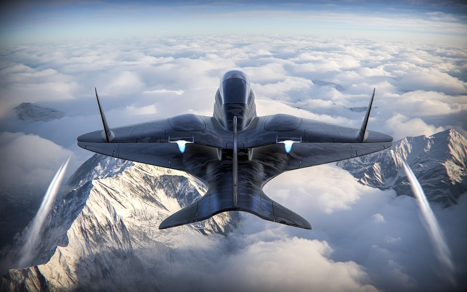
Why a 3D Printed Hawk-Shaped Drone Flies Differently
A hawk silhouette is not decoration. The wing planform of a soaring raptor has a high aspect ratio, a swept leading edge, and separated primary feathers at the tip. Those primaries act as individual small lifting surfaces, and they break up the tip vortex that would otherwise pull energy off the wing. On a 3D printed hawk-shaped drone, the same tips are printed as discrete fingers or slotted flaps, so the airframe inherits part of that vortex control instead of fighting it.
The body shape does a second job. A real hawk's torso is a smooth teardrop with no hard corners, which keeps the boundary layer attached over a wide angle-of-attack range. When the printed shell copies that curve, stall arrives later and more gently than on a boxy fuselage of the same frontal area. That matters for a drone that has to glide, hover, and turn inside a small site.
Flapping changes the picture. A bird-mimicking airframe often carries a flexible wing driven by a crank or a servo horn. Printed ribs with graded thickness let the wing twist along the span, so the outboard section pitches down as it sweeps forward. That passive twist reduces the peak load on the root spar, and it is the reason printed wings can survive cycles that would crack a stiff molded shell.
None of this is free. A realistic silhouette costs surface area, and surface area costs drag at speed. The shape that glides well at 8 m/s becomes a brake at 20 m/s. Decide the flight envelope first, then pick the silhouette.
Scale sets the limit. Below roughly 300 mm wingspan, printed feathers are too small to hold shape and the vortex benefit disappears. Above about 1,200 mm, printed shells need internal spars anyway, and the weight advantage over a machined or molded airframe narrows.
Material and Wall Thickness Limits
Most printed hawk airframes are built from PA12 or PA12 with 20–30 percent short glass fiber. The glass raises stiffness and reduces creep under a parked wing load, at the cost of a rougher surface and slightly lower elongation. Carbon-filled nylon is stiffer still, but it is brittle in thin ribs and abrasive to nozzles, so it suits spars and mounts rather than feather tips.
Wall thickness is the tightest constraint. Below 1.0 mm, thin ribs warp as they cool and the printed part will not hold a straight trailing edge. Above 2.5 mm, mass climbs faster than stiffness, because stiffness in bending scales with the cube of thickness while mass scales linearly. A 1.4–1.8 mm skin with a 0.8 mm rib is a workable starting point for a 600 mm span wing.
Layer direction decides where the part breaks. Fused filament parts are weakest between layers, so align the build so that bending stress runs along the extrusion path, not across it. On a wing spar printed flat, the layers lie along the span and the part takes bending well. Printed standing up, the same spar splits at the first hard landing.
Post-processing closes the gap between printed and machined parts. Bead blasting at low pressure removes support scars on the leading edge. A thin primer fills layer lines and can cut skin friction noticeably on a small airframe. For hinge points, shaft bores, and motor mounts, machine the mating faces to ±0.005 mm and press or bond the printed shell onto them.
Moisture is the quiet failure mode. Nylon absorbs water from the air, and a wet printed wing gains mass and loses stiffness over a season. Sealing the shell with a thin coating keeps the part stable and makes the surface easier to clean between flights.
Mass Budget and Center of Gravity
Printed airframes fail on mass long before they fail on strength. A 600 mm span wing printed in glass-filled PA12 typically lands between 120 g and 200 g per side depending on wall thickness and infill. The battery, motor, and flight controller usually add more than the airframe itself, so every gram saved in the shell buys flight time directly.
Infill is the lever. Gyroid or hexagonal infill at 15–25 percent carries most of the bending load in a printed wing, while solid skins at the leading edge handle impact. Going above 35 percent infill adds mass with almost no gain in stiffness, because the outer skin already carries the bending.
Balance matters more than total mass. A bird-shaped airframe has most of its area behind the wing root, and the tail surfaces sit far from the center of gravity. If the printed tail is heavy, the battery has to move forward, which pushes the nose down and costs trim drag. Weigh each printed section before assembly and shift material rather than adding ballast.
Servo and hinge placement sets the control response. A flapping or sweeping wing needs its actuator close to the root spar, or the printed ribs twist under load and the control surface lags the command. Keep the pushrod run short, and reinforce the printed horn with a machined insert.
A simple rule holds up in practice: keep the printed airframe below 40 percent of all-up weight. Past that share, the wing loading climbs and the glide performance that justified the bird shape disappears.
Printed Shell vs Machined Frame vs Molded Shell
Compare airframe routes for a small bird-shaped drone before committing to tooling.
| Criterion | 3D printed shell | CNC machined frame | Injection molded shell |
|---|---|---|---|
| Best part count | 1–20 units | 1–200 units | 5,000+ units |
| Tooling cost | None | None | High, paid up front |
| Wall thickness range | 1.0–2.5 mm | 3 mm and up | 0.8–2.0 mm |
| Design change cost | Reprint only | Reprogram and recut | New mold |
| Surface as built | Visible layer lines | Ra 0.8–1.6 μm typical | Smooth from tool |
| Typical lead time | 3–5 days | 3–5 days | Weeks after tooling |
| Best for | Complex organic shapes | Load-bearing joints | High-volume repeat runs |
When to Print and When to Machine
Print the shell when the shape is organic, the batch is under a few hundred units, and wall thickness can stay between 1.0 mm and 2.5 mm. Machine the spars, hinge bores, and motor mounts, because those joints need ±0.005 mm and metal stiffness. If you are past 5,000 units a year, move the shell to a mold and keep the printed route for prototypes.
Common Questions
How realistic can a 3D printed hawk-shaped drone look in flight?
From 30 m away, a printed shell with printed feather tips and a matte gray-brown finish reads as a bird to most observers, especially when the wings flex. Up close, layer lines and support marks are visible unless the shell is sanded and primed.
Realism in flight comes more from motion than from surface detail. A wing that twists and a tail that sweeps sell the illusion better than a perfect print.
Which material should we start with?
Start with PA12 or glass-filled PA12. It tolerates thin ribs, handles impact, and prints with predictable shrinkage. Move to carbon-filled nylon only for spars and mounts, where stiffness matters more than toughness.
Avoid PLA for anything that flies. It creeps in a warm car and cracks at the first hard landing.
Can printed parts hold a motor mount?
Not on their own. Print the mount body, then bond or bolt a machined aluminum or stainless insert into it. The insert takes the thread load and the heat path; the printed shell takes the shape and the vibration damping.
What wall thickness keeps a printed wing straight?
Between 1.4 mm and 1.8 mm for the skin, with ribs around 0.8 mm. Thinner skins warp during cooling and the trailing edge waves. Thicker skins add mass without adding much bending stiffness.
How do we keep the design confidential?
Uploads are handled as confidential and an NDA can be signed before files move. If the airframe is a product you plan to sell, ask for the NDA first and keep the CAD revision history on your side.
Do printed airframes need CNC work at all?
Yes, at the interfaces. Hinge bores, shaft seats, and any face that bolts to a metal part should be machined to ±0.005 mm and inspected before assembly. Printed surfaces alone will not hold a bearing fit.
Send Us Your Airframe Files
Upload the shell and the mating metal parts together. We review print orientation, wall thickness, and machined interfaces, then send a quotation with free DFM analysis within 12 hours.
12-hour quote100% inspectionNDA on request
More From the Shop Floor
We publish setup notes, tooling trials and inspection data from the factory floor.











