
Tools Pre Adjustment Measurement: How Offline Tool Setters Work
Tools pre adjustment measurement happens away from the spindle, so the machine receives a length, a diameter and a runout value it can trust. This page covers the mechanism, the accuracy limits and the cases where offline setting is the wrong choice.
In this article
- 1
- 2
- 3
- 4
- 5
- 6
What a Tools Pre Adjustment Measurement Instrument Actually Measures
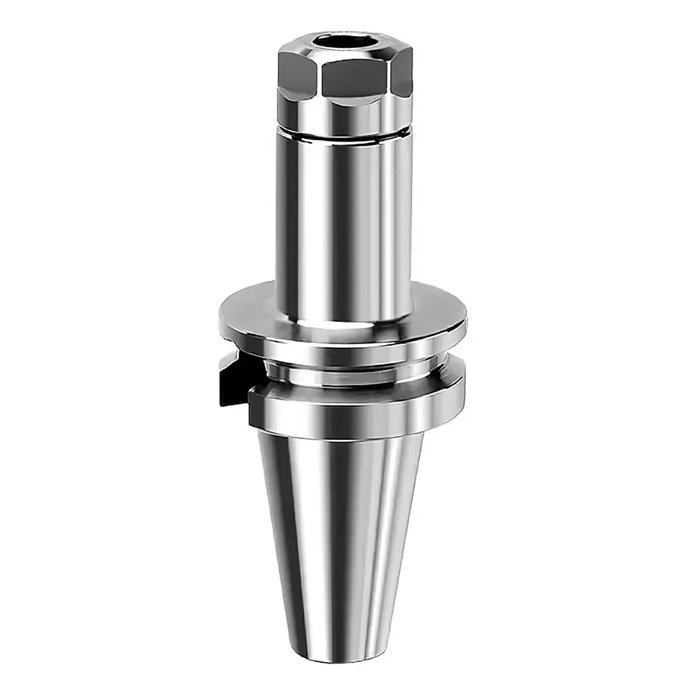
A tools pre adjustment measurement instrument is a bench unit that holds a tool holder in a known reference seat and reads the cutting edge against a scale or a vision system. The holder taper sits in a spindle replica, so the geometry the machine will see is reproduced off the machine. Three numbers come out: gauge length, cutting diameter and edge runout.
The reference seat is the whole trick. A CAT 40, BT 40 or HSK holder is located on the same taper and flange faces as in the spindle, which means the measurement is tied to a physical datum rather than to a software guess. If the seat wears, every tool measured on it drifts by the same amount.
A typical bench unit resolves length to 0.001 mm and diameter to 0.001 mm on the digital display. That resolution is not the same as accuracy. The real accuracy budget covers seat wear, holder taper cleanliness, spindle thermal state and how the operator zeros the probe. A displayed 0.001 mm with 0.01 mm of real drift is a common and expensive illusion.
Gauge length is measured from the holder gauge plane to the tool tip. Diameter is measured across the cutting edges, not across the shank. Runout is the total indicator reading as the tool rotates one full turn. Each value feeds a different offset in the control, and mixing them up is the fastest way to scrap a first article.
Two Sensing Methods and Where Each One Fits
Contact setters push a hardened stylus against the cutting edge and record the position when the circuit closes. They work on almost any geometry, including odd rake angles and chipbreaker forms that a camera cannot trace cleanly. The stylus leaves a tiny mark on soft coatings, which matters for PVD-coated carbide used in finishing.
Optical setters project a magnified shadow of the tool onto a screen or a CMOS sensor. The operator lines the edge up with a crosshair or lets software detect it. No contact means no marking, and edge condition is visible at the same time, so chipped corners and built-up edge get caught before the tool goes in the spindle.
Optical units struggle with dark, highly reflective or deeply fluted edges where the shadow boundary is ambiguous. Contact units struggle with fragile edges, tiny micro-tools below 0.5 mm, and any tool where stylus pressure could shift the insert in its pocket.
In a shop running mixed work, the practical split is optical for small drills, taps and finishing cutters, contact for roughing mills and anything with a broken-up edge profile. Some benches combine both heads on one column, which removes the argument entirely.
Why Offline Setting Beats Touching Off in the Spindle
Touching a tool off against a workpiece or a setting block inside the machine costs spindle time. A VMC standing idle while an operator creeps a 12 mm end mill down onto a gauge block is not making chips. On a 16-machine floor, that idle time compounds across every setup of the day.
Offline setting also moves the job to a bench where the operator can see the edge. Under spindle flood coolant, a chipped corner looks the same as a good one. On the bench, at 20× magnification, it does not. Catching one chipped insert before a run is cheaper than scrapping the parts it would have cut.
The third gain is repeatability across shifts. Once a tool is measured and its offset written into the tool data page, any operator can load it and get the same result. Spindle touch-off depends on who is standing at the control, how much pressure they use and whether the gauge block is clean.
The machine still verifies. Most controls re-check a tool against a probe after the first few parts or on a fixed interval. Offline setting does not replace in-machine probing; it feeds it a starting value that is already close, which shortens the probe cycle and reduces the chance of a crash.
The Accuracy Budget and Where It Leaks
Bench accuracy claims usually quote the scale, not the system. A 0.001 mm scale on a column that is bolted to a bench in a warm shop will not deliver 0.001 mm at the tool tip. Thermal growth of a 300 mm steel column is roughly 0.003 mm per 1 °C, so a morning-to-afternoon swing of 4 °C eats the entire budget.
Seat contamination is the next leak. A single chip or a film of coolant on the taper face tilts the holder and shifts the reading. Wipe the taper and the seat before every measurement. A 0.02 mm chip under the flange can move the tip by more than 0.05 mm on a long holder.
Holder-to-holder variation is real even within one brand. Taper grind tolerance, pull-stud length and retention knob condition all move the datum slightly. The bench measures the holder in front of it, not an idealized holder, which is correct as long as the same holder goes into the same spindle.
The final leak is the machine itself. Spindle thermal growth between a cold start and a two-hour warm-up can exceed the bench error by an order of magnitude. Measure tools at the same thermal state the machine will run in, or accept that offsets need refreshing after warm-up.
Boundary Conditions: When Offline Setting Is the Wrong Call
Very long tools are a problem. A 400 mm boring bar or an extended reach cutter deflects under its own weight, and the deflection depends on how it is clamped on the bench versus how it sits in the spindle. The measured length will be close; the measured runout will lie.
Micro-tools below 0.3 mm are another boundary. Optical systems at that scale need high magnification and a stable mount, and stylus contact is out of the question. At that size, in-machine laser tool setting is usually the better route because it measures the tool in the exact condition it will cut in.
Reground tools drift. Every regrind removes material from the tip and changes both length and diameter. If the shop does not re-measure after every regrind, the offset in the control is stale and the first part of the run is a gamble. Re-measure is not optional for reground cutters.
Single-piece prototype work is a gray zone. If a job uses three tools and runs for twenty minutes, the setup time for offline measurement may exceed the savings. For a 10,000-part run with twelve tools, the arithmetic flips completely and offline setting pays back inside the first shift.
Choosing a Setting Method by Tool and Job
Match the method to the tool type, the batch size and the tolerance the job actually needs.
| Tool or job | Best method | Why |
|---|---|---|
| Ø 0.2–0.5 mm micro drill | In-machine laser | No contact, measured in cutting condition |
| Ø 12 mm roughing end mill | Contact bench setter | Handles chipbreaker geometry, no marking risk |
| Finishing cutter, PVD coated | Optical bench setter | No stylus mark on the coating |
| 400 mm boring bar | In-machine probe | Bench runout reading is not reliable at that length |
| Reground end mill | Bench setter, every regrind | Length and diameter both changed |
| 3-tool prototype, 20 min run | Spindle touch-off | Setup time outweighs the saving |
| 12-tool run, 10,000 parts | Optical bench setter | Idle spindle time dominates cost |
| Deep-fluted tap | Contact bench setter | Shadow boundary is ambiguous optically |
The Short Version
If the job runs long enough to keep the spindle busy, set tools offline on a bench and let the machine probe confirm. If the job is three tools and twenty minutes, touch off in the spindle and move on.
Common Questions
How often should the bench reference seat be checked?
Check it against a master holder or a calibration pin on a fixed schedule, and any time a holder is dropped or a reading looks off. In a shop running two shifts, a monthly check is a reasonable starting interval.
If the seat shows wear, every tool measured on it carries the same error. Log the deviation so you can tell a seat problem from a holder problem.
Does offline setting remove the need for in-machine probing?
No. The bench gives the control a starting offset. The probe confirms it on the machine, where spindle growth and clamping repeatability are also in play.
Running both is the normal practice. The bench value shortens the probe cycle and gives the operator a number to compare against when something looks wrong.
What tolerance can we realistically hold with bench setting?
For a well-maintained bench and a clean holder, length repeatability around 0.005 mm is realistic. That matches the ±0.005 mm shop tolerance we work to on the machines.
Below that, the limit is usually thermal drift and holder variation, not the scale on the column.
Can we set tools while the machine is cutting?
Yes, and that is the main economic argument. The bench work happens in parallel with spindle time, so the next job is ready before the current one finishes.
Plan the tool list so the operator knows which holders to measure next. A printed setup sheet beats a verbal handover.
Do we need a different setter for HSK and for BT holders?
It depends on the bench. Some units take interchangeable seats for CAT, BT, HSK and Capto, and the seat swap is a few minutes. Others are built for one taper family.
If your floor runs mixed tapers, buy the version with swappable seats. It costs less than a second bench.
What about runout after the tool is in the spindle?
Bench runout measures the holder and tool as an assembly. Once clamped in the spindle, the taper fit adds its own error, usually a few micrometres on a clean spindle.
If finish or hole size drifts, check spindle taper condition before blaming the bench reading.
Send Us Your Tool List
Upload your drawings and tool list, and we will come back with a quote and a DFM note within 12 hours. No minimum order quantity, from one prototype to 10,000+ parts.
12-hour quote±0.005 mm tolerance100% inspection
More From the Shop Floor
We publish setup notes, tooling trials and inspection data from the factory floor.











