Three Axis CNC Milling Machine: 7 Proven Steps to Better Parts
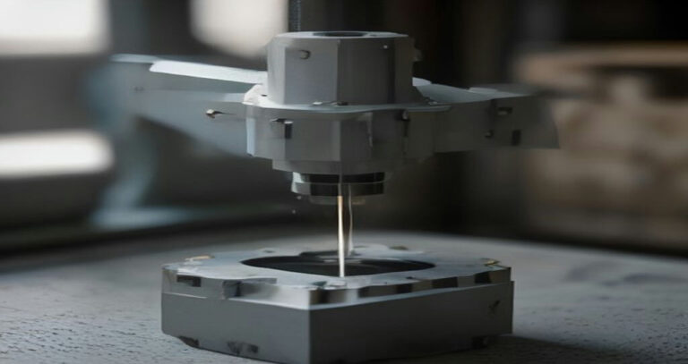
A Three Axis CNC Milling Machine is still the workhorse of most machine shops, and for good reason. It is rigid, predictable, and cheaper to run than a 5-axis. But the same machine can produce parts that hold tenths all day or scrap that drifts out of tolerance by noon. The difference is rarely the iron. It is the setup, the tooling, the workholding, and how honestly you plan around what the machine cannot reach. This guide is for engineers, programmers, and shop leads who need a Three Axis CNC Milling Machine to deliver parts that pass inspection the first time.
Most problems start before the first chip. A vise bolted to the table, a tool list copied from the last job, and no thought about which features need a second op. That approach works until a pocket wall tapers, a hole walks, or a reamed bore comes in oval. A Three Axis CNC Milling Machine holds position well under stable conditions, but every setup change resets your error budget. Stack three or four of them and the tolerance disappears.
The article walks through seven steps, from reading the part against the machine’s real capability to final inspection. You will see how to plan workholding around rigidity, choose tools for the material and feature, control thermal drift, and decide when a Three Axis CNC Milling Machine is the wrong choice. We also cover the limits: undercuts, deep cavities, and features that need five sides in one setup. Knowing those limits early saves the most money.
- How to judge part geometry against a Three Axis CNC Milling Machine before quoting
- Setup and workholding decisions that protect tolerance across multiple ops
- Tooling, speeds, and feeds that match the machine rather than the catalog
- When to stop fighting the process and move the job to a different platform
Nothing here is theoretical. These are the checks and habits that separate shops with repeatable output from shops chasing scrap rates. Used well, a Three Axis CNC Milling Machine remains one of the most cost-effective tools on the floor. Used carelessly, it becomes a tolerance lottery. The seven steps that follow are how to stay on the right side of that line.
What a Three Axis CNC Milling Machine Really Does
A Three Axis CNC Milling Machine moves the cutting tool, the workpiece, or both along three linear axes: X, Y, and Z. X and Y position the tool across the table, while Z controls depth. That is the entire motion envelope. No rotary tilt, no fourth-axis indexing, just three perpendicular directions of travel.
That simplicity defines the work the machine does well, and the work it cannot touch without help. Understanding the boundary is the first step toward quoting and programming 3-axis work correctly.
The work envelope is a rectangular box. Every point the tool can reach sits inside the X, Y, and Z travel limits, minus the space consumed by vises, fixtures, and clamps. A typical vertical machining center in the 40-taper class might offer X travel around 600 to 1000 mm, Y around 400 to 600 mm, and Z around 400 to 600 mm, though sizes range widely from compact drill-tap machines to large gantry-style mills.
The spindle approaches the part from one direction only: straight down along Z. That is what people mean by 3-sided access. The tool can machine the top face and the four vertical walls of a part in a single setup, but it cannot reach the underside or any face that requires the tool to come in at an angle.
Square-shoulder geometry is where this layout shines. Because the tool axis stays perpendicular to the table, a Three Axis CNC Milling Machine produces true 90-degree corners, flat floors, and pockets with vertical walls. An end mill cutting a shoulder leaves a clean square corner with no witness marks from a tilted tool. In many shops, that geometric predictability is the main reason 3-axis work stays on 3-axis machines.
Speed and cost follow from the same simplicity. Three linear axes mean fewer servo dynamics to manage, simpler toolpaths, and shorter setup times. A Three Axis CNC Milling Machine typically runs faster in cut than an indexed 5-axis machine on the same feature, because there is no rotary table to position and no re-post for each orientation. Programming is also cheaper. CAM output for 3-axis toolpaths is easier to verify, and operators can prove out a program with less risk of a rotary collision.
Fixturing is simpler too. A vise, a set of toe clamps, or a vacuum plate often does the job. That keeps setup time and fixture cost down, which matters on prototype and low-volume work.
So where does 3-axis stop working? Several feature types force a rotary table or a second operation:
- Undercuts and side-access holes that the Z-axis tool cannot reach from above
- Compound angles, such as a face tilted in two directions at once
- Features on the bottom or back of a part that require repositioning
- Radial holes and slots around a cylindrical body
- Contoured surfaces with continuous curvature across more than one plane
Each of these either needs a fourth axis to index the part, a second op on another machine, or a 5-axis platform that tilts the tool. A Three Axis CNC Milling Machine can still make the part, but the setup count climbs and accuracy drifts with every re-clamp.
The practical rule many shops use: if the part can be machined from one direction, keep it on a Three Axis CNC Milling Machine. If it needs four or more sides, or any angled face, move it to a machine with rotary motion. That decision affects cycle time, fixturing cost, and inspection strategy.
Getting the boundary right early saves rework. A Three Axis CNC Milling Machine is the workhorse for flat, prismatic, and square-shouldered parts, and it stays the cheapest way to make them. The skill is knowing when the geometry has outgrown it.
Background reading: the Numerical control overview is a useful reference on the fundamentals.
Materials and Tolerances You Can Hold
A Three Axis CNC Milling Machine handles a wider material range than most shops give it credit for. Aluminum, mild and alloy steel, stainless, brass, and engineering plastics all run well on a rigid three-axis platform with the right speeds, feeds, and tooling. The limits come less from the machine’s axes and more from how the material behaves under heat and cutting force.
Aluminum 6061 and 7075 cut fast and hold tight numbers. A well-set-up Three Axis CNC Milling Machine can often hold +/-0.001 in. on aluminum features, with flatness around 0.0005 in. over a few inches when the vise and fixturing are solid. Surface finish on aluminum typically lands between 63 and 125 Ra, and can reach 32 Ra with a finishing pass and sharp tooling.
| Material | Typical Tolerance | Typical Finish (Ra) |
|---|---|---|
| Aluminum (6061/7075) | +/-0.001 in. | 63-125, down to 32 |
| Mild / alloy steel | +/-0.001 to +/-0.002 in. | 63-125 |
| Stainless (303/304/17-4) | +/-0.001 to +/-0.002 in. | 63-125 |
| Brass | +/-0.001 in. | 32-63 |
| Engineering plastics | +/-0.002 to +/-0.005 in. | 63-125 |
Steel and stainless tighten the window. They cut with more force, so tool deflection shows up sooner, especially on long reach or small-diameter end mills. Stainless work-hardens, which means a Three Axis CNC Milling Machine has to keep the cutter moving through the material rather than rubbing. Brass is the easy one, holding +/-0.001 in. and finishes near 32 Ra without much fuss.
Plastics are their own problem. Acetal, PEEK, and similar materials move with temperature and clamp pressure. Tolerances of +/-0.002 to +/-0.005 in. are realistic on a Three Axis CNC Milling Machine, but thin walls and long parts may need stress relief or a rough-and-finish sequence to stay in spec.
Positional accuracy on a healthy machine often sits around +/-0.0005 in., and repeatability is frequently better. Those numbers describe where the tool goes, not what the part measures. Flatness, parallelism, and squareness depend on setup, fixturing, and how the part reacts to being cut. A tight position spec means little if the part lifts off the vise when the clamps release.
Thermal growth is where long runs get ugly. A spindle and ballscrews warm up over the first hour or two, and the machine physically grows. On a long batch, that drift can push a feature that started in spec out of tolerance by mid-run, even though nothing changed in the program. Shops that hold tight numbers over hours often warm up the machine first, control coolant temperature, and check a known feature at intervals rather than trusting the first article.
Tool deflection erodes tolerance in a different way. A long end mill or a small cutter pushed hard will bend, and the wall it leaves behind is not where the program says it is. This shows up as taper on deep pockets, inconsistent slot widths, and chatter marks. Reducing depth of cut, shortening tool overhang, and using a stiffer holder all help. If the geometry demands a lot of reach or complex angles, it may be worth comparing against Precision 4 Axis CNC Machining Services before committing the job to a three-axis setup.
The practical takeaway is to match tolerance to material and geometry, not to a wish list. A Three Axis CNC Milling Machine can hold +/-0.001 in. consistently on aluminum with good fixturing and a warmed-up spindle. Push the same callout onto a long stainless part with thin walls, and the real limit is the process, not the machine. Engineers who know where that line sits get parts that pass inspection the first time, and sourcing teams get quotes that hold up. When you need a shop that understands those limits, GreatLight builds precision parts across prototypes and production runs.
Workholding Setups That Cut Cycle Time
On a Three Axis CNC Milling Machine, the spindle only moves in X, Y, and Z. Every minute the table sits idle while an operator loads a vise is a minute the spindle earns nothing. Workholding is where most shops find their easiest cycle-time wins, because the fix is usually setup design, not faster feeds.
A standard machine vise is fine for one-offs and job-shop work. For repeat production, though, the vise becomes the bottleneck. Each part gets clamped and unclamped by hand, jaws get dialed in, and the operator stands at the door for the whole run. If you are running more than a few dozen identical parts, the vise is costing you money.
Fixture plates solve part of that problem. A dedicated plate holds multiple parts in fixed positions, so the Three Axis CNC Milling Machine can machine one pocket while the operator loads the next. Because every pocket is located from the same datum, tool offsets stay consistent across the batch. Soft jaws machined in place do the same job for round or irregular parts: bore the jaw profile with the actual cutter and work offset you will use in production, and you get repeatable location without indicating every blank.
Vacuum chucks are worth a look when parts are thin, flat, and non-porous. They clamp across the whole face, which reduces the bowing and chatter that mechanical clamps can cause on plate work. The trade-off is holding force. Light depths of cut, sharp tooling, and clean sealing surfaces are not optional with vacuum. For most shops, vacuum handles the first op on flat stock; vises or fixtures handle the second.
Tombstones and pallet changers are where a Three Axis CNC Milling Machine starts running unattended. A tombstone is a vertical column mounted on the table with fixture faces on two or more sides. Load four sides with parts, and the machine mills one face while the operator loads another. A pallet changer goes further: two pallets swap at the spindle, so the machine never stops for a load. One operator can keep a Three Axis CNC Milling Machine cutting through a full batch, and with enough pallets staged, through a lights-out shift.
The rules for making this work are simple and unforgiving:
- Locate every part from the same hard stop or pin, never from a vise jaw that gets bumped.
- Machine soft jaws and fixture pockets in place, on the machine, with the production tool.
- Keep chips out of locating features. A single chip under a part throws the whole batch.
- Probe or touch off the first part of each pallet, not just the first part of the shift.
- Balance clamp force. Too much distorts the part; too little lets it move under load.
Tool life and chip evacuation matter more on a Three Axis CNC Milling Machine running lights-out, because nobody is watching. A broken tool at 2 a.m. means scrap, not a pause. Set conservative feed and speed limits for unattended hours, use through-spindle coolant where the setup allows, and add tool-break detection if the control supports it. The same principles behind any Milling (machining) operation apply, just with less margin for error.
None of this requires exotic hardware. A pair of matched vises, a fixture plate, and a tombstone can meaningfully raise the output of a Three Axis CNC Milling Machine without adding a single spindle hour. Start with the part you run most often, build the fixture around it, and measure the cycle time before and after. The numbers usually make the case on their own.
Choosing the Right Three Axis CNC Milling Machine
That logic applies to machine selection too. The right Three Axis CNC Milling Machine is the one whose work envelope, spindle, and rigidity match the parts you actually quote, not the parts you dream about. Start with the spindle interface, because it constrains everything downstream.
CAT40 and BT30 are the two tapers you will see most often on a Three Axis CNC Milling Machine in a job shop. CAT40 uses a steeper, larger taper with a longer gauge line, so it holds bigger face mills and heavier tool assemblies with less deflection. BT30 is smaller and lighter, which lets the machine accelerate tools faster and change them quicker, but it gives up stiffness at the cutting edge.
| Feature | CAT40 | BT30 |
|---|---|---|
| Typical max tool diameter | Often 80-100 mm with clearance | Usually 50-63 mm |
| Best for | Steel, cast iron, heavy roughing | Aluminum, small parts, high tool changes |
| Tool change speed | Slower, heavier drawbar load | Fast, lighter mechanics |
| Rigidity at the cut | Higher | Moderate |
Way construction matters just as much. Box ways are hardened, ground, and scraped surfaces with a large contact area. They damp vibration well and hold up under interrupted cuts in steel or iron. Linear rails roll on recirculating bearings, run faster with less stick-slip, and need less maintenance, but they can flex more under heavy radial loads. Many shops running a Three Axis CNC Milling Machine on mixed work choose linear rails for speed and box ways for heavy material removal.
Table size and travel decide what you can actually mount. A 500 x 400 mm table sounds generous until you add a vise, a fixture plate, and a rotary table. Measure the largest part plus workholding plus tool clearance before you commit. Also check spindle nose to table distance, because tall fixtures and long drills eat that space fast.
Match spindle power and torque to your material removal rate. Aluminum cuts fast at high rpm with modest torque. Steel and stainless need lower rpm and more torque, so a machine rated for high speed but low torque will stall or chatter when you push a face mill. Ask for a torque curve, not just a peak power number.
Here is a quick checklist for quoting a machine to a real job mix:
- Largest part envelope plus workholding, measured, not estimated
- Heaviest material and the deepest radial and axial cut you run
- Tool taper and the largest face mill or drill you use
- Spindle speed range and torque at the low end
- Way type and the surface finish tolerance your parts demand
- Tool changer capacity against your typical setup count
- Control compatibility with your existing programs and posts
Run the checklist against two or three candidates and the decision gets easier. A Three Axis CNC Milling Machine that fits your job mix will outproduce a bigger, faster machine that fights your parts. If you are weighing a retrofit against a new purchase, a Bridgeport Milling Machine CNC Conversion can stretch an existing frame, but only if the ways and spindle still hold tolerance. Otherwise, spec the Three Axis CNC Milling Machine around the work you already have on the floor. GreatLight builds precision machining programs around exactly that kind of fit.
Toolpath Strategies for 3-Axis Efficiency
Roughing on a Three Axis CNC Milling Machine lives or dies on one number: radial engagement. Most legacy CAM defaults bury the cutter at 50 percent of its diameter or more. That works on forgiving aluminum with a rigid setup, but it spikes cutting force, heat, and chatter everywhere else. Adaptive clearing changes the math. Instead of full-width passes, the tool enters with a controlled arc and holds a constant chip load through the whole cut.
Typical adaptive parameters run 10 to 25 percent radial engagement with an axial depth of cut one to two times the tool diameter. That sounds backwards if you learned on traditional stepdowns. It is not. The cutter removes the same volume, but the load spreads along more of the flute, so heat leaves with the chip instead of soaking into the edge. Tool life in hard materials can improve substantially compared to a buried full-width pass.
Slotting is the classic weak point. A full-width slot traps chips, and recutting them is what kills carbide. Trochoidal slotting solves this with a circular tool motion that advances forward in small increments. The cutter never sees more than a fraction of its diameter in engagement, and the chips have room to clear. On a Three Axis CNC Milling Machine, this is the safest way to cut deep slots in stainless, titanium, and hardened tool steels.
High-feed cutters take a different route to the same goal. These tools use a small lead angle and a chip-thinning geometry, so you can push feed rates hard while keeping depth of cut shallow. The result is lower radial load and less deflection on long reaches. They are not a substitute for adaptive clearing in every case, but they are excellent for face milling and for finishing floors where you want speed without side load.
| Strategy | Radial Engagement | Axial Depth | Best Use |
|---|---|---|---|
| Adaptive clearing | 10-25% of diameter | 1-2x diameter | Pocket roughing |
| Trochoidal slotting | 5-15% of diameter | Full slot depth | Deep slots |
| High-feed cutter | 60-80% of diameter | Shallow | Facing, floors |
Here is where 3-axis beats 5-axis for the same pocket. A contoured 5-axis toolpath can reach into corners and follow walls with less hand finishing, but it adds rotary motion, longer cycle time, and more setup risk. For a pocket with a flat floor and vertical walls, a well-planned Three Axis CNC Milling Machine roughing pass removes the bulk faster with fewer variables. Save the 5-axis work for geometry that genuinely needs it.
Stepover and depth of cut are not independent knobs. Increase axial depth and you must reduce radial engagement to keep the chip load sane. Reduce both and you are just rubbing. The practical rule: pick the deepest axial cut the tool and holder can take without chatter, then set radial engagement from the material and the chip thinning factor. Verify with the CAM simulation before the tool ever touches stock.
Programmers who treat a Three Axis CNC Milling Machine as a roughing workhorse get more from it. Use adaptive clearing for bulk removal, trochoidal motion for slots, and high-feed cutters for floors. Then let a Three Axis CNC Milling Machine finish the walls and floors in a separate, lighter pass. Splitting rough and finish keeps tool wear predictable and makes the second op easier to hold to tolerance. It also keeps your Three Axis CNC Milling Machine running at rates the spindle and fixture can actually support.
Inspection and Quality Control Workflow
Qualifying a new program is not the same as proving the machine can cut metal. The goal is proving the process holds size, repeatably, across the whole lot. A Three Axis CNC Milling Machine removes material in one setup per face, so every re-fixture is a chance for datum shift. Your inspection plan has to catch that shift before it reaches a customer.
Start with a first-article inspection. Run one part, let it cool to room temperature, and measure every dimension on the print, not just the toleranced ones. Thermal growth matters here: aluminum at 20 degrees C above ambient can move several thousandths on a long feature. If the shop floor runs warm, note the part temperature on the FAIR so the numbers mean something later.
In-process probing changes the economics of a job. On a Three Axis CNC Milling Machine with spindle-mounted touch probe capability, you can verify a bore or a pocket wall between operations without breaking the setup. The probe reads the actual surface, feeds that offset back into the control, and the next tool cuts to the corrected position. This does not replace final inspection. It stops you from producing forty scrap parts before anyone notices the tool wore past its limit.
For critical dimensions, follow up on a coordinate measuring machine. A CMM gives you the geometry the probe and calipers cannot: true position, perpendicularity, profile of a surface. Match the CMM setup datums to the machining datums in the program. If the program zeros off a vise jaw and the CMM zeros off a corner hole, you are measuring two different parts.
Documentation is where aerospace and medical work separates from general job shop work. Most of these programs require a traceable chain from raw stock to finished part. For each lot, plan to retain:
- Material certification and heat lot numbers tied to the work order
- First-article inspection report with nominal, actual, and tolerance for each characteristic
- Tool list with offsets and any in-process probe results logged by serial number
- CMM reports for critical features, plus the program revision that produced them
- Machine calibration records and operator identification for the run
Keep the revision control tight. When engineering changes a print, that is a new program revision, a new first article, and a new CMM report. Do not let an operator edit offsets at the control and call it a process change. Offsets compensate for tool wear. They do not fix a bad program.
How often should you re-verify? For a stable process, first article plus periodic checks during the run is often enough. For tight-tolerance work, some shops inspect the first part, the last part, and every tenth piece in between. The right interval comes from your own process capability data, not from a rule of thumb borrowed from someone else. If the Three Axis CNC Milling Machine holds a characteristic across twenty consecutive parts with margin, you can widen the check interval. If it drifts, tighten it and find out why.
One more step that pays off: re-inspect after any setup break. A tool change, a fixture reset, a new operator taking over mid-lot. Each one resets the risk. A quick probe check on one known feature tells you within seconds whether the process is still where you left it. That habit alone removes many of the surprises that show up at final inspection.
If your parts need five-axis contouring on top of the three-axis work, the same rules apply with tighter datum control. For that class of work, it helps to look at how a Precision 5 setup is qualified, because the inspection logic carries over directly.
Release the lot only when the first article, the in-process data, and the CMM results all agree. Anything less and you are shipping hope. A Three Axis CNC Milling Machine is predictable when the process is controlled, and inspection is what proves the control held. Build the paperwork into the job, and the Three Axis CNC Milling Machine becomes a repeatable source of good parts rather than a source of rework.

Cost Drivers and Where 3-Axis Saves Money
Every quote you get for a machined part is built from four numbers: setup time, fixture cost, tooling, and the machine hourly rate. How those four stack up decides whether a Three Axis CNC Milling Machine or a 5-axis machine is the cheaper route. The part geometry, not the salesman, makes that call.
Setup time is usually the biggest swing factor on small batches. A three-axis job typically needs one vise or a simple plate fixture, a few edge finds, and a tool touch-off. A 5-axis job often needs a tombstone, a self-centering fixture, or a zero-point system, plus verification that the rotary axes are dialed in. That extra hour or two of setup gets spread across the whole lot, so on a run of ten parts it can dominate the price.
Fixture cost follows the same logic. Three-sided access usually means the part sits in a standard vise or a soft jaw set you can cut in-house for modest money. Five-axis work frequently demands custom workholding that clears the rotary table through the full range of motion, and that fixture may cost more than the parts it holds. On a prototype or low-volume order, that fixture is pure overhead.
Tooling is closer between the two, but not identical. A 5-axis machine often runs longer reach tools to clear the trunnion, and long tools deflect more, so shops slow down to hold tolerance. A Three Axis CNC Milling Machine can use short, rigid end mills and run them harder. If the part only needs three-sided access, you are paying for reach you do not need.
Machine hourly rates are where the gap is clearest. A 5-axis machining center carries a higher rate because the machine costs more, the programmer costs more, and the setup is more sensitive. In many shops that rate runs higher than a three-axis vertical mill. Multiply a higher rate by a longer cycle and the difference compounds fast.
The table below shows the typical pattern for a simple bracket with features on three faces:
| Cost driver | 3-axis route | 5-axis route |
|---|---|---|
| Setup time | One vise, quick edge find | Tombstone or zero-point, axis verification |
| Fixture cost | Standard vise or soft jaws | Custom workholding, often complex |
| Tooling | Short, rigid end mills | Longer reach tools, slower feeds |
| Hourly rate | Lower | Higher |
The reverse is also true, and it is worth saying plainly. If the part has features on five or six faces, or needs compound angles, a three-axis setup means multiple operations, multiple re-fixtures, and multiple chances to lose datum. Each re-fixture adds setup time and stack-up error. In that case a single 5-axis op can beat three separate three-axis ops on total cost and on tolerance.
There is a middle path many shops use. A Three Axis CNC Milling Machine handles the flat faces, pockets, and holes, then the part moves to a 5-axis for the angled features. Splitting the work keeps the cheap operations cheap and reserves the expensive machine for what only it can do. That is often the lowest total cost on a mixed-feature part.
Programmer time belongs in the math too. A three-axis toolpath is straightforward to write and easy to prove out. Five-axis toolpaths need collision checking, post-processor confidence, and often a trial cut. That engineering time is real money, and on a one-off part it can exceed the machining time itself.
So the rule of thumb holds: if the part only needs three-sided access, the Three Axis CNC Milling Machine is usually the lower-cost route. If it needs four or more faces with tight relationships between them, price the 5-axis option before you commit. Let the geometry pick the machine, and the quote will hold up. A well-planned Three Axis CNC Milling Machine job also keeps the paperwork clean, which keeps the cost predictable on the next order.
When to Move Up to 4 or 5 Axis
A Three Axis CNC Milling Machine cuts on X, Y, and Z only. The tool always approaches the work from one direction, and the part usually gets repositioned by hand whenever a new face needs machining. That constraint is fine for a large share of prismatic work. It stops being fine the moment geometry demands an approach angle the spindle cannot reach without a re-fixture.
Four-axis adds rotation about one linear axis, typically A or B. Five-axis adds a second rotary axis, so the tool can tilt and swivel relative to the part. Both let you reach features in a single setup that would otherwise need two, three, or four separate operations on a Three Axis CNC Milling Machine.
Here are the features that usually justify the jump.
- Deep angled holes. A cross-drilled lubrication passage entering at 30 or 45 degrees to the part face is awkward on three axes. You can sometimes get there with a sine plate or an angle fixture, but the setup eats time and the drill tends to walk on an inclined surface. A tilting spindle or trunnion holds the angle precisely and drills it in one pass.
- Undercuts. Any feature that sits behind a wall the tool cannot clear from above is a candidate for rotary motion. Three-axis workarounds exist, such as T-slot cutters or lollipop tools, but they limit reach and often force a second setup. Rotary axes simply rotate the part to expose the undercut.
- Compound curves. Impellers, turbine blades, and contoured housings with curvature in two directions at once cannot be machined efficiently with a fixed vertical spindle. Ball-nose toolpaths on a Three Axis CNC Milling Machine leave witness lines and long cycle times because the tool center stays vertical. Tilting the tool keeps the contact point optimal and shortens the path.
- Five-sided work in one setup. When four or five faces of a part carry features, each re-fixture adds stack-up error and labor. Rotary axes let you machine all of them from one datum. Position tolerance improves because the part never leaves the vise or chuck.
Rough decision rule: if a part needs more than two setups on a Three Axis CNC Milling Machine, or if any single feature requires a custom angle fixture, run the numbers on a four- or five-axis alternative. For prototypes, the calculus often favors the higher-axis machine even at a higher hourly rate, because setup dominates the quote. A one-off bracket with three angled faces might need hours of fixturing on three axes versus minutes of cutting on five.
For production volumes, the answer flips more often than people expect. Once a fixture is built and proven, a Three Axis CNC Milling Machine running three cheap setups can beat a five-axis cycle if volumes are high and the part is stable. The crossover often lands somewhere in the low hundreds of units, but it depends on feature count, tolerance, and how many faces carry work. High-mix, low-volume shops lean toward five-axis because changeover cost drops. High-volume shops with a dedicated part number lean toward three-axis because the fixture cost amortizes away.
One more factor: tolerance stack. Every setup introduces a new datum and a new chance for error. If a drawing calls for true position across multiple faces, fewer setups means fewer contributors to the stack. That argument alone pushes many aerospace and medical jobs to five-axis even when the cycle time looks worse on paper.
If you are unsure, send the drawing and let the shop quote both routes. A good process engineer will tell you honestly whether a Three Axis CNC Milling Machine handles the part or whether the geometry has outgrown it. At GreatLight, we run three-, four-, and five-axis equipment side by side, so the recommendation comes from what the part actually needs rather than what is sitting idle.
Putting Your Three Axis CNC Milling Machine to Work
The seven steps above are not theory. They are the same sequence good shops run every day: understand what the machine can hold, match material and tolerance to the process, fixture the part so it stays put, pick a machine that fits the envelope, cut with a sensible toolpath, inspect against the print, and know when 3-axis stops being the cheap answer. Get those right and a Three Axis CNC Milling Machine will hold tight tolerances, run predictable cycle times, and stay profitable on the parts it was bought for.
Most of the cost savings come from boring things. Fewer setups, shorter tool changes, cutters that last, and inspection that catches a drift before it becomes scrap. None of that requires a new machine. It requires discipline on the floor.
Before you quote the next job, run a quick check:
- Does the part actually need a fourth or fifth axis, or just a better fixture?
- Are tolerances realistic for the material and the Three Axis CNC Milling Machine in the shop?
- Is the toolpath leaving money on the table in roughing time?
- Is inspection built into the process, or bolted on at the end?
If the answer to any of those is unclear, that is usually where the margin leaks. When you need a partner who runs this playbook daily, GreatLight handles prototypes through production with 5-axis milling, turning, and full inspection. Send your drawings and let us quote the job against a Three Axis CNC Milling Machine process, or tell us if the part really needs more axes. Either way, you get a straight answer and a number you can plan around.