
01
Gear whine at cruise
Tooth contact lands on the wrong part of the flank. The pattern was never checked, so the set runs noisy at 60–80 km/h and the customer hears it before we do.
We machine ring and pinion gear sets for differentials, axles and gear drives. Hypoid and spiral bevel geometry, cut and lapped as a matched pair, then checked on the test stand before it leaves the floor.

Most ring and pinion complaints trace back to one of these.
Tooth contact lands on the wrong part of the flank. The pattern was never checked, so the set runs noisy at 60–80 km/h and the customer hears it before we do.
Tooth form and mounting distance change together. A revised housing or a new pinion offset moves the pattern, and the old setup no longer cuts a usable flank.
Root fillet radius and case depth are not controlled. Teeth chip at the toe under load, and the axle comes back long before the mileage target.
Runout, backlash or hardness falls outside the print. Every rejected set costs a teardown, a re-shim and a line stoppage you did not plan for.
A ring gear only works with the pinion it was lapped to. We treat them as a single part number from the first operation.

Ring and pinion gears turn driveshaft rotation 90 degrees to the axle, and the offset pinion of a hypoid set lets the driveshaft sit below the axle centerline. That offset is what buys ground clearance and lets the gear run quieter than a straight bevel set at the same ratio.
We cut tooth flanks on simultaneous 5-axis machining centers, then verify the contact pattern in a lapping compound check. Mounting distance, pinion offset and spiral angle stay tied to your housing, not to a generic fixture.
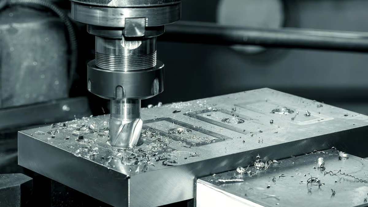
Cutting gets the geometry close. Lapping gets the set quiet. We run ring and pinion together in abrasive compound until the contact patch covers the right share of the flank, then keep them together through heat treatment, finishing and packing.
Each pair carries the same serial number on both parts. If a set is ever replaced under warranty, the replacement is lapped to the same pattern, not pulled from a bin of lookalike gears.
Ratios follow the tooth counts you specify. A 4.10 ratio means the driveshaft turns 4.10 times for each wheel revolution, so the ring carries 41 teeth against a 10-tooth pinion.
Pick the geometry first, then the ratio.
| Gear type | Typical use | What it gives you |
|---|---|---|
| Hypoid | Automotive axles, light truck | Quiet running, driveshaft below axle center |
| Spiral bevel | Industrial gear drives, marine | High torque, no offset, simple housing |
| Straight bevel | Slow-speed drives, hand tools | Lowest cost, louder at speed |
| Hunting ratio | Street, mixed duty | Even tooth wear across the full ring |
| Non-hunting ratio | Race, fixed duty | All tooth combinations in one revolution |
| Partial non-hunting | Off-highway, towing | Fewer combinations, longer pattern life |
One shop for the gear set and the parts that hold it.
Hypoid and spiral bevel pairs from Ø60 mm up, cut and lapped to your ratio and backlash.
No-offset bevel gears for industrial drives, pump units and marine gearboxes.
Carrier and cover machining with bore alignment held to the gear mounting distance.
Splines, bearing journals and threads turned in one setup on mill-turn centers.
Turned blanks, keyways and bolt circles ready for your cutting operation.
One-off pairs for dyno and field testing before you commit to a production run.
| Item | Range | Notes |
|---|---|---|
| Max part size | 4,000 mm | Large travel 4,000 × 400 × 150 mm |
| Tolerance | ±0.005 mm | ±0.0002 in on critical diameters |
| Surface finish | Ra 0.2–0.8 μm | Fine finish on journals and bores |
| Materials | 4140, 4340, 8620, 17-4PH | Case-hardening steels on request |
| Ratios | 2.26:1 to 6.17:1 | Other ratios by tooth count |
| Inspection | 100% before shipment | Reports on request |
Fifteen years of gear, shaft and housing work across three wholly-owned plants in Dongguan and Singapore.
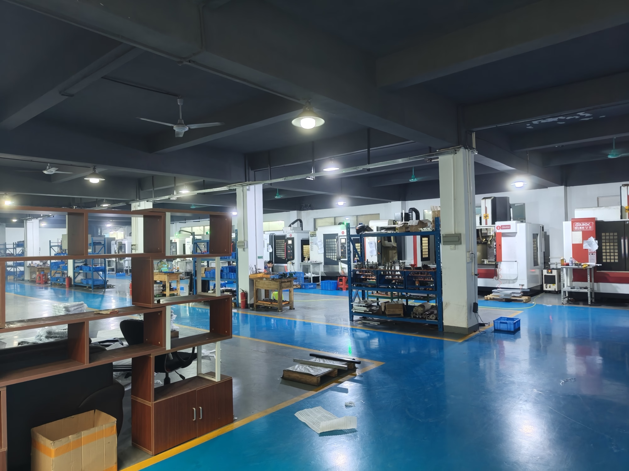
Including 16 simultaneous 5-axis centers, 12 four-axis mills and 16 mill-turn centers under one roof.
Send a drawing and get a price with free DFM feedback inside 12 hours. Production can start within 24 hours.
IATF 16949:2016 and ISO 9001:2015 certified, with in-process monitoring on every gear lot.
From a single lapped pair to 10,000+ part runs, on the same equipment and the same inspection plan.
Uploads are encrypted, access is limited to the assigned cell, and an NDA is available on request.

Quiet operation across the cruise range, backlash held to the print, IATF paperwork with each lot.

Higher ratios for torque multiplication, tooth roots sized for shock loads, lapped pairs marked and serialed.

Spiral bevel sets for pump and conveyor units where the housing fixes the mounting distance.
One-off pairs for dyno work, cut to a target ratio so the team can test before tooling is committed.
In a hunting set, any one pinion tooth eventually contacts every ring tooth, so wear spreads across the whole ring. It takes several ring revolutions to run through all combinations.
In a non-hunting set, each pinion tooth returns to the same ring teeth every revolution, so all combinations are reached in one turn. Partial non-hunting sits between the two: a pinion tooth meets a few ring teeth, then a different group on the next revolution.
Divide ring tooth count by pinion tooth count. A 41-tooth ring on a 10-tooth pinion gives 4.10:1, meaning the driveshaft turns 4.10 times per wheel revolution.
Lower numerical ratios give higher top speed and better fuel economy with slower acceleration. Higher numerical ratios trade top speed for acceleration and towing capacity. Pick from the duty cycle, not from habit.
Yes. We cut to your tooth counts, so the ratio follows from the numbers you specify rather than from a catalog.
Send both counts and the housing mounting distance. If the combination loads the pinion unusually hard, we will say so during DFM review.
Always. The two parts are lapped together and carry the same serial number through heat treatment, finishing and packing.
A replacement pair is lapped to the same pattern, so you are not shimming around a mismatched set.
Common choices are 4140, 4340 and case-hardening grades such as 8620, plus 17-4PH stainless for corrosion resistance.
Material callout drives the heat treat and finishing route, so tell us the hardness target and the environment the gear sees.
We check the contact pattern in lapping compound, measure backlash on the lapped pair, and verify runout and mounting distance against your drawing.
Inspection is 100% before shipment, with raw material checks, in-process monitoring and a final report available on request.
There is none. We run a single lapped pair for prototype or dyno work, and the same cell handles 10,000+ part runs.
That means your test pair and your production parts come off comparable equipment, so the pattern you approve is the pattern you get.
Send a drawing and we return a quotation with free DFM analysis within 12 hours. Production can start within 24 hours of approval.
Typical shipping is 3–5 days for machined parts. Timing depends on heat treatment and lapping queue, which we confirm with the quote.
Tell us the ratio, the housing mounting distance and the material. We will come back with a price and DFM notes on the same drawing.
12-hour quote100% inspectionNo minimum orderNDA on request
Trusted by engineers and manufacturers worldwide










Upload your 3D model or 2D drawing and get a quotation with a free DFM analysis. Maximum processing size 4,000 mm.
CNC Metals 13 grades
CNC Plastics 10 grades
Machines & processes 12 options
Surface & post-processing 10 options
Material: not selected Machine: not selected Post-process: not selected
Fill in this short form and we'll open WhatsApp with your message ready to send. We only use these details to reply to you.
Nothing is sent until you press send inside WhatsApp.