
Horizontal Turning and Milling Machine Tools: How They Work
A horizontal turning and milling machine holds the part on a horizontal spindle and brings a live tool to it. That single setup removes turning, milling, drilling, and tapping steps from separate machines. This guide explains the mechanics, the tooling, and the part geometry that actually justifies the setup.
What horizontal turning and milling actually does
A conventional lathe spins the workpiece and pushes a static tool along the Z axis. A horizontal turning and milling machine keeps the same horizontal spindle but adds a powered tool turret or a B-axis head. The part still rotates, but now a spinning cutter can move in X, Y, and Z while the part turns.
That combination changes what one setup can finish. On a plain lathe, any flat, slot, or cross hole means a second operation on a mill. On a mill-turn center, the same program turns the OD, mills a hex, drills an off-axis port, and taps it before the part leaves the chuck.
The horizontal spindle orientation matters for chip evacuation. Chips fall away from the cutting zone instead of sitting on the workpiece, which helps on deep bores and long shafts. It also lets the machine take heavier radial cuts without the part deflecting under its own weight.
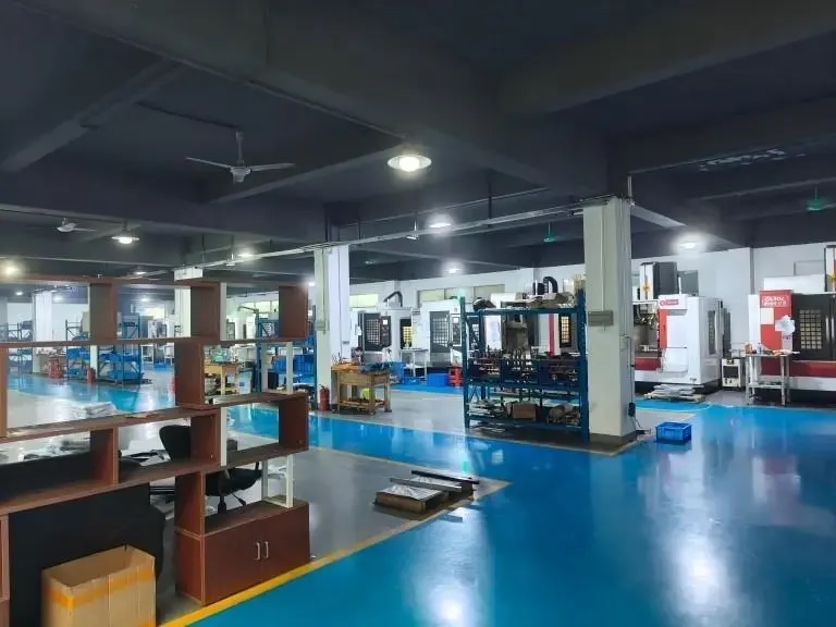
We run 16 mill-turn centers among 127 high-precision CNC machines. Maximum processing size is 4,000 mm, and the Ø400 mm rotary table covers most round parts that need cross features. Tolerance holds at ±0.005 mm on turned diameters when the setup is rigid.
This is not a universal answer to every part. A simple turned bushing with no cross features runs faster on a plain lathe. The value appears when the part has two or more features that would otherwise need re-fixturing.
Live tooling and the B axis
A live tool is a driven holder mounted in the turret. It spins a drill, end mill, or tap while the turret indexes to position it. Standard live tools run on the turret's own motor; higher-end machines drive them through a separate spindle for more torque.
The B axis tilts the tool head around the Y axis, usually from -30° to +120°. That tilt lets a single end mill reach a face, an angled port, and a cross hole without re-clamping the part. On parts with compound angles, this is the difference between one setup and three.
Tool count limits what you can finish in one cycle. A 12-station turret with six live stations covers most turned-and-milled parts. If the part needs 20 distinct tools, plan for a second operation or a tool-change pause.
Spindle speed for live tools is lower than a dedicated mill. Expect 4,000–8,000 rpm on most turret-driven holders. That is fine for drilling and light milling, but heavy face milling belongs on a 3-axis or 5-axis mill.
Coolant through the live tool helps on deep holes. Without it, chips pack in the flutes and the drill walks. We spec through-coolant holders on any cross hole deeper than 3× diameter.
Which part shapes justify the setup
The clear win is a round part with cross features. A hydraulic manifold, a motor shaft with a keyway and a cross-drilled port, or a valve body with angled ports all fit. The turning holds concentricity; the live tool cuts the cross features in the same datum.
Parts with tight concentricity between an OD and a bore are a second fit. Doing the bore on a mill after turning means re-chucking and losing 0.02–0.05 mm of alignment. One setup keeps the runout under 0.01 mm.
Long shafts with features at both ends are a third case. A subspindle catches the part and machines the back side without a manual flip. That saves a second op and the handling damage that comes with it.
Some parts look like a good fit but are not. A flat plate with a few holes is faster on a 3-axis mill. A part under 20 mm long with no cross features runs better on a Swiss-type lathe. The mill-turn center earns its rate on complexity, not on simple round work.
Material matters too. Aluminum 6061 and 7075 cut fast on live tools with high rake angles. Stainless 316 and 17-4PH work-harden, so keep the feed per tooth above 0.05 mm and never dwell. Titanium TC4 needs lower surface speed and more coolant.
Accuracy, surface finish, and inspection
Turning accuracy on a rigid horizontal turning and milling setup lands at ±0.005 mm on diameters. Live-tool milling on the same part is looser, typically ±0.02 mm, because the turret adds a second kinematic chain. Plan your tolerances around that split.
Surface finish follows the same pattern. Turned surfaces reach Ra 0.8–1.6 μm with a sharp insert and the right feed. Milled surfaces from a live tool usually sit at Ra 1.6–3.2 μm. If a milled face needs Ra 0.8 μm, add a finishing pass or a separate polishing step.
Thermal drift is the main enemy on long cycles. A 40-minute cycle warms the spindle and the ballscrews, and the part grows. We hold ±0.005 mm by letting the machine warm up and by checking the first part hot, not cold.
Inspection is 100% before shipment. That covers raw material check, in-process monitoring, and a final dimensional report. Reports go out on request with the parts.
The qualification rate across these cells is 99.99%. That number comes from the inspection loop, not from the machine alone. A mill-turn center without in-process checks will drift on a long run.
Cycle planning and cost drivers
Cycle time on a mill-turn center is not the sum of the separate operations. It is usually 30–50% shorter because the part never moves. That saving is real on medium and high volumes, and it shrinks on one-off parts where programming dominates.
Programming time is the hidden cost. A part with live-tool features takes longer to program than a plain turned part. On a one-off prototype, the programming hour can cost more than the machining hour. That is why we run a free DFM analysis within 12 hours before quoting.
Fixture cost drops to near zero. The chuck or collet holds the part, so no soft jaws, no custom plate, no second-op fixture. On a 5,000-part run, that removes a real line item.
Tool cost per part rises. Live tools wear faster than static turning inserts, and a broken 3 mm end mill stops the cycle. Budget for more tool changes and keep spares at the machine.
The break-even point sits around 200–500 parts for a part with two cross features. Below that, two separate operations on a lathe and a mill are often cheaper. Above it, the mill-turn center wins on both time and accuracy.
When to pick which machine
Match the part geometry to the process before you quote.
| Part feature | Best process | Why | Typical tolerance |
|---|---|---|---|
| Plain round, no cross holes | CNC lathe | No live tool needed | ±0.005 mm |
| OD plus cross-drilled port | Mill-turn center | One setup, one datum | ±0.005 mm turned |
| Flat plate with holes | 3-axis mill | No rotation needed | ±0.02 mm |
| Compound angled ports | 5-axis or B-axis mill-turn | Tool tilt reaches the angle | ±0.02 mm |
| Long shaft, both ends | Mill-turn with subspindle | No manual flip | ±0.01 mm runout |
| Small part under 20 mm | Swiss-type lathe | Guide bushing support | ±0.005 mm |
| Prototype, 5 pieces | Lathe plus mill | Programming cost lower | ±0.02 mm |
| 5,000 parts, 3 features | Mill-turn center | Cycle time down 30–50% | ±0.005 mm |
The short version
If the part is round and has cross features that must stay concentric, run it on a horizontal turning and milling machine. If it is a simple round part or a flat plate, a plain lathe or a 3-axis mill will cost you less and finish just as well.
Common questions
What is the difference between a mill-turn center and a lathe with live tooling?
A lathe with live tooling drives the cutter from the turret and usually works in X, Z, and a limited Y. A mill-turn center adds a full Y axis and often a B axis, so the tool can tilt and reach compound angles.
The practical split is feature count. Two or three cross features fit on a live-tool lathe. A part with angled ports and a milled flat needs the B axis.
Can a horizontal turning and milling machine hold ±0.005 mm on milled features?
Not usually. The turned diameters hold ±0.005 mm because the part and tool sit on one kinematic chain. Milled features come off the turret, which adds a second chain and typically lands at ±0.02 mm.
If a milled face needs tighter than ±0.02 mm, plan a finishing pass on a dedicated mill or accept the looser callout on the drawing.
How deep can a cross hole go with a live tool?
Without through-coolant, keep the depth under 3× diameter. Beyond that, chips pack in the flutes and the drill walks off center.
With through-coolant holders and a peck cycle, 5–8× diameter is realistic in aluminum and mild steel. Stainless work-hardens, so keep the feed per tooth above 0.05 mm and avoid dwelling.
Does the horizontal spindle limit part size?
No. Horizontal turning and milling centers handle bar work and chuck work up to 4,000 mm on our machines. The horizontal layout actually helps on long shafts because chips fall clear of the cut.
The limit is swing over the bed and the rotary table diameter. A Ø400 mm rotary table covers most round parts with cross features.
What materials run well on live tooling?
Aluminum 6061, 7075, and 2024 cut fast with high rake angles. Brass C36000 and copper C110 also run clean. Stainless 303 and 17-4PH work if feeds stay high and coolant reaches the edge.
Titanium TC4 and Inconel need lower surface speed, more coolant, and a rigid setup. They run, but cycle time climbs and tool wear is the cost driver.
How many parts before a mill-turn center beats two separate operations?
For a part with two cross features, the break-even sits around 200–500 parts. Below that, the programming time on the mill-turn center offsets the cycle-time saving.
Above that volume, the cycle time drops 30–50% and the fixture cost disappears, so the mill-turn center wins on both time and accuracy.
Send us the drawing
Upload your part and we will run a free DFM analysis within 12 hours, then quote the process that fits the geometry.
12-hour quote100% inspectionNo minimum order quantityNDA on request
More from the shop floor
We publish setup notes, tooling trials and inspection data from the factory floor.











