
Overview of CNC Machining Center
An overview of CNC machining center design for engineers and buyers: how the machine moves, where the practical limits sit, and how to tell which parts belong on a 3-axis, 4-axis or 5-axis machine before you send a drawing out for quote.
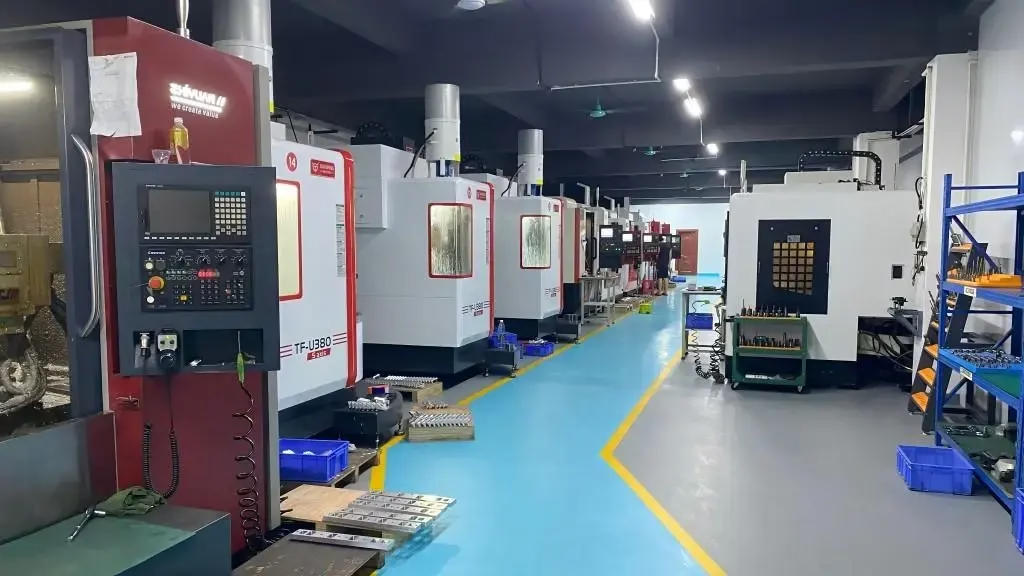
What a CNC machining center actually is
A CNC machining center is a machine tool with a rotating spindle, an automatic tool changer and at least three programmable linear axes. The controller reads G-code, drives ball screws and linear guides, and cuts material with a milling cutter, drill or boring head. A lathe spins the part; a machining center spins the tool. That single difference drives most of the decisions that follow.
The spindle sits on a ram or column. The table carries the workpiece, sometimes on a rotary table. Tool changers hold anywhere from 12 to 60+ tools, so a part can move from roughing to drilling to tapping without an operator touching it. That is why a machining center beats a manual mill on repeatability, not just speed.
Axis count tells you what the machine can reach in one setup. Three axes cover prismatic parts with features on one face. A fourth axis adds rotation around X, so you can cut four sides without re-fixturing. Five simultaneous axes let the tool approach a surface from an angle instead of straight down, which matters for contoured faces, deep pockets and undercuts.
The frame matters as much as the controller. Cast iron and polymer concrete bases damp vibration. Linear guides trade some damping for speed. A heavy frame and a 15,000 rpm spindle behave differently from a light frame at 24,000 rpm, and the difference shows up in surface finish, not in the spec sheet.
- 1Spindle spins the toolThe workpiece stays on the table, unlike a lathe.
- 2Tool changer cuts idle time12 to 60+ tools per job, no manual swaps.
- 3Axis count sets reach3-axis, 4-axis and 5-axis solve different geometry.
- 4Frame controls finishMass and damping decide chatter, not just rpm.
Where tolerances and surface finish come from
Published machine accuracy is not the same as the tolerance you can hold on a real part. A machine may position to ±0.003 mm in a warm room on a test piece, but the part you get depends on fixturing, tool wear, thermal drift and how the stock was prepared. On a well-set-up job we hold ±0.005 mm on critical features, and we measure that with a CMM or a vision system, not with the machine's own readout.
Surface finish follows cutting parameters. Ra 1.6–3.2 μm is a normal as-machined finish from a sharp end mill at moderate feed. Ra 0.8–1.6 μm needs finer stepover, a smaller chip load and usually a finishing pass with a different tool. Ra 0.2–0.8 μm calls for slow feed, light depth of cut and a rigid setup, and sometimes a secondary operation such as lapping or polishing.
Speak in ranges, not single numbers. Tolerances tighter than ±0.005 mm over a long part get expensive fast because thermal growth alone can eat the budget. A 300 mm aluminium part grows about 0.007 mm for every 1 °C change. If your drawing asks for ±0.01 mm across 4,000 mm, the honest answer is that the process cannot guarantee it as a routine result.
Inspection is where the number becomes real. We check raw material on arrival, monitor in-process, and inspect 100% before shipment, with reports on request. For fit-critical features, agree on the datum and the inspection method before cutting, not after the parts arrive.
- 1Machine spec ≠ part toleranceFixturing, wear and heat add error.
- 2Finish follows parametersStepover and chip load set Ra, not spindle rpm alone.
- 3Watch thermal growthRoughly 0.007 mm per 1 °C on 300 mm aluminium.
- 4Fix the datum earlyInspection method should be agreed before cutting.
Why setup count drives cost and lead time
Every time a part leaves the fixture, you lose position. Each new setup needs a fresh datum, a new zero and a new first-article check. Two setups on a simple bracket are normal. Five setups on a housing mean five chances for stack-up error and five blocks of machine time. This is the single biggest lever an engineer can pull before quoting.
A 4th axis or a 5-axis machine removes setups rather than adding them. A part that needs four faces cut in three setups on a 3-axis mill can often run in one on a 5-axis. Fewer setups means tighter true position between features, shorter lead time and less fixture cost. The trade is programming time and a higher hourly rate.
Design for the setups you can afford. Add a clear datum face, or a boss the fixture can grip. Avoid thin walls under 1 mm unless the geometry demands it, because they vibrate and force light passes. Deep pockets with an aspect ratio over 4:1 need a long, thin tool that deflects, so open the corners with a larger radius where the function allows.
If a feature tolerances off a face that is machined in a later setup, you are stacking error on purpose. Reference critical dimensions to the first datum instead. A drawing that respects setup order usually comes back cheaper and with fewer questions.
- 1Fewer setups, better positionEvery re-fixture adds stack-up error.
- 25-axis cuts setupsFour faces in one setup is common.
- 3Avoid thin wallsUnder 1 mm walls chatter and need light passes.
- 4Open deep pocket cornersLarger radii reduce tool deflection.
Materials and how they change the cut
Aluminium is the default for prototypes and most enclosures. Grades like 6061, 7075, 2024 and 6082 cut fast, hold good finish and take anodizing well. 7075 is stronger but less weldable and more prone to stress movement when you remove a lot of stock. For die-cast style parts, ADC12 is the casting grade, not a billet grade.
Stainless grades behave differently from each other. 303 machines freely, 304 work-hardens if the tool rubs, and 316L is common in medical and marine work. 17-4PH gives high strength after heat treatment. Keep the cutter engaged, use a positive rake and never dwell, because dwell is what hardens the surface under the tool.
Steel covers a wide band. 1018 and 1045 are general-purpose; 4140 and 4340 are for stressed parts; A36 is structural plate, not a precision alloy. Titanium, Inconel and magnesium sit at the hard end. Ti-6Al-4V and the TA grades cut slowly with heavy coolant and sharp tools, while magnesium AZ31B and AZ91D machine quickly but need chip control because fine magnesium chips are a fire risk.
Plastics are mostly about heat. POM and PEEK hold tolerance well; ABS and PC scratch easily; carbon fibre wears tools fast. Tell us the material and the function. A part that sees load should not be specified in the same grade as a cosmetic cover.
- 1Aluminium is the default6061, 7075, 2024, 6082, ADC12.
- 2Stainless work-hardensKeep the cutter engaged, never dwell.
- 3Titanium cuts slowSharp tools and heavy coolant.
- 4Plastics are heat-limitedPOM and PEEK hold tolerance best.
Which machine fits the part
Match geometry and tolerance to axis count before you request a quote.
| Part situation | Best fit | Why | Watch out |
|---|---|---|---|
| Features on one face, simple shape | 3-axis mill | Lowest hourly rate, fast setup | Extra setups for other faces |
| Four sides, moderate volume | 4-axis mill | One rotation, no re-fixture | Rotary table eats work envelope |
| Contoured faces, undercuts | 5-axis simultaneous | Tool angles to the surface | Higher programming cost |
| Shafts and round parts | Mill-turn center | Turning and milling in one setup | Not for large prismatic blocks |
| Long parts up to 4,000 mm | Large gantry or travel mill | 4,000 × 400 × 150 mm travel | Thermal error over long spans |
| Tight true position, many features | 5-axis, one setup | No stack-up between faces | Needs probing and warm-up |
The honest trade-off
If the part has features on one face and a normal tolerance, a 3-axis machine is the cheaper and faster choice. If true position between four or more faces decides whether the assembly fits, pay for 5-axis and one setup instead of three.
Questions engineers ask next
Can you hold ±0.005 mm on every feature?
No, and no shop can. We hold ±0.005 mm on critical features with the right setup and inspection, and looser on non-critical ones.
Put the tight tolerance on the dimensions that matter for fit or function. That keeps cost and lead time down without risking the assembly.
How does stock removal affect the final part?
Removing a lot of material releases internal stress, so the part can move after machining. Thin plates and long extrusions move most.
For stress-sensitive parts we take roughing and finishing passes in separate operations, and sometimes add a stress-relief step. Tell us if the part must stay flat.
Which materials should not be specified for appearance parts?
Magnesium and titanium are poor cosmetic choices unless you plan a finish. Both show tool marks and oxidation easily.
6061 aluminium and 303 stainless take bead blasting, brushing and anodizing well, so they are safer for visible covers.
What file format do you need for a quote?
STEP or IGES for 3D geometry, plus a 2D PDF with datums, tolerances and notes. A native CAD file helps if you have one.
A drawing with no GD&T leaves the datum open to interpretation, which is where most first-article disagreements start.
How fast can parts ship?
Quotation and free DFM analysis come back within 12 hours. Production can start within 24 hours, and parts normally ship in 3–5 days.
Lead time depends on material availability, setup count and finishing. Anodizing or plating adds a secondary step.
Do you sign an NDA before I send files?
Yes. Uploads are secure and confidential, and we sign an NDA on request before reviewing your drawings.
Send the NDA with your files and we return the signed copy with the quote.
Send a drawing, get a real answer
Quotation and free DFM analysis within 12 hours, with the machining route explained before you commit.
12-hour quote100% inspectionNo minimum order quantityNDA on request
More from the shop floor
We publish setup notes, tooling trials and inspection data from the factory floor.











