
New CNC Machining Center: How It Machines Your Parts
A new CNC machining center is a machine, not a service package. This page explains what its spindle, axes, and structure actually do to a part. Read it to judge which parts belong on 5-axis, which belong on 3-axis, and where the limits sit.
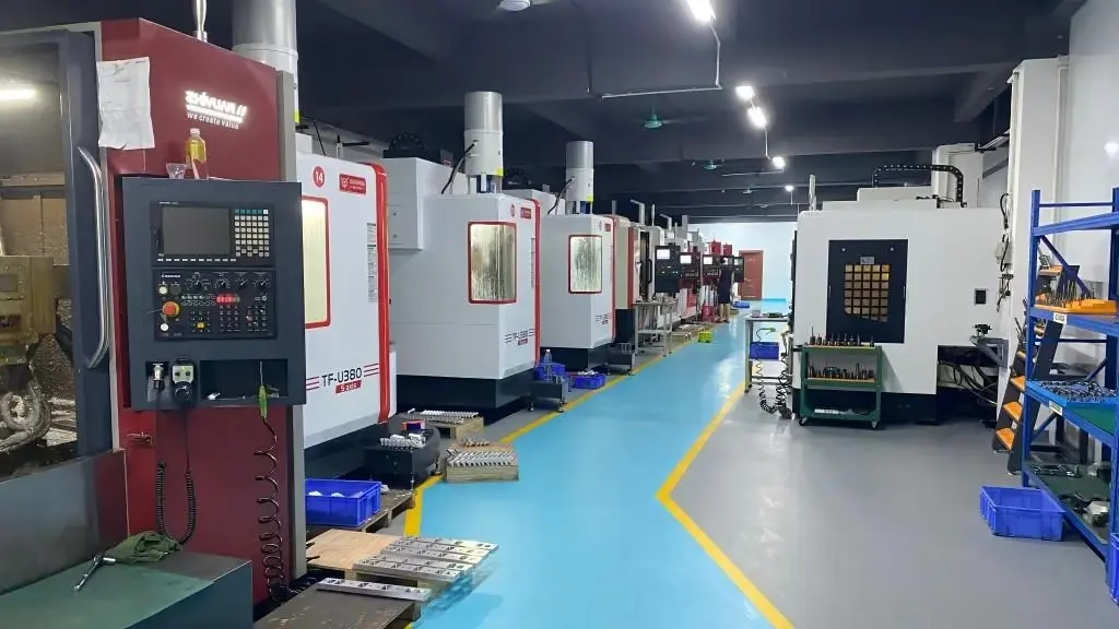
What the machine actually does
A machining center is a milling machine with an automatic tool changer and a control that moves the part or the spindle along several axes. Programs are written offline, loaded, and repeated. That repeatability is the real change. The machine does not get tired on part 400, so the first part and the last part should measure the same if the process is stable.
The spindle is the cutting engine. Its top speed sets the surface finish you can reach with small tools; its torque sets how deep you can cut in steel. A 12,000 rpm spindle with a small tool will give a better finish on an aluminium pocket than a 6,000 rpm spindle, but it will not drive a Ø50 mm face mill through 4140 at the same depth.
Rigidity decides accuracy more than the control does. A machine with a heavy cast base and linear guides resists chatter when a long end mill reaches deep into a cavity. Chatter shows up as a rippled wall and a Ra number that drifts. The control cannot correct a machine that is flexing.
Tool changers matter for throughput, not for geometry. A 24-station magazine lets a job run through many features without a manual stop. For a one-off prototype this saves minutes. For a 10,000-part run it saves weeks.
- 1Spindle speed sets finishHigher rpm with small tools reaches Ra 0.2–0.8 μm on aluminium.
- 2Rigidity sets accuracyA stiff frame holds ±0.005 mm through a deep cut.
- 3Tool changer sets cycle timeMore stations means fewer manual interruptions.
3-axis, 4-axis, and 5-axis: what each one solves
A 3-axis machine moves X, Y, and Z. The tool always points down. This is the cheapest and fastest way to cut a part with features on one side or with shallow steps you can reach from above. Most flat brackets, plates, and housings start here.
A 4-axis machine adds a rotary table, usually around the X or Y axis. Now the part can be indexed to four sides without being unclamped. That removes one setup per side and removes the position error that comes with re-clamping. A Ø400 mm rotary table covers most pump bodies and valve blocks.
A 5-axis machine adds a second rotary axis, so the tool can tilt. Tilting lets a short, stiff tool reach a deep side wall or an undercut that a 3-axis machine cannot touch. It also lets the tool stay normal to a curved surface, which spreads the cut and improves finish on contoured faces.
The trade is not free. Five-axis motion is slower per cut and the programming is harder. A part that can be reached in three setups on a 3-axis machine may still be cheaper there. Five-axis wins when the geometry needs it or when the setup count would otherwise be high.
- 13-axisFlat parts, one dominant face, lowest cycle time.
- 24-axisParts with features on four sides, one clamping.
- 35-axisUndercuts, deep cavities, contoured surfaces, tight position between faces.
Rigidity, heat, and why tolerance drifts
Every cut pushes back. The force bends the tool, the holder, and the part. On a light finishing pass the bending is small. On a heavy roughing pass in 4140 it is not. If the part is thin, the wall moves away from the cutter instead of the cutter cutting it, and the finished wall is tapered.
Heat is the second source of drift. Aluminium carries heat away quickly, so it stays close to its nominal size. Stainless and titanium hold heat at the cutting edge, which wears the tool and changes the effective diameter. A tool that measured Ø10.000 mm at the start of a run may cut Ø9.980 mm by the end.
The way to hold ±0.005 mm is not to push harder. It is to take a roughing pass, let the part settle, and take a light finishing pass with a sharp tool. On stable aluminium parts this is routine. On a thin 316L housing it needs a planned sequence and sometimes a stress-relief step.
Inspection closes the loop. We check raw material on arrival, monitor dimensions during the run, and inspect 100% before shipment. Reports are available on request. If a dimension is drifting, we see it before the parts ship, not after.
- 1Thin walls deflectSupport the part or cut in stages to avoid taper.
- 2Tool wear shifts sizeCompensate or change tools mid-run on long jobs.
- 3Finishing pass sets final sizeRough close, then take a light pass at ±0.005 mm.
Which materials change the plan
Aluminium is the easy case. Grades 6061 and 7075 cut fast, hold tight tolerance, and take a good finish. A 5-axis centre can run a complex aluminium housing in one setup and hold ±0.005 mm across faces. This is where most prototype and low-volume work sits.
Stainless 303 and 304 cut cleanly but work-harden if the tool rubs. Feeds must stay aggressive enough to cut, not rub. 17-4PH in the H900 condition is harder and slower; it is common in medical and aerospace parts where strength matters more than cycle time.
Titanium Ti-6Al-4V and Inconel are the hard cases. They cut slowly, generate heat at the edge, and wear tools fast. A part in Inconel may need three or four tools where an aluminium part needs one. This is not a reason to avoid the material, but it is a reason to plan the tool path before quoting.
Plastics behave differently again. POM and PEEK cut cleanly but move with temperature. ABS and PC can melt at the edge if the tool dwells. For these, sharp tools and a fast feed beat a slow, cautious pass.
- 1Aluminium 6061 / 7075Fast, stable, holds tight tolerance.
- 2Stainless 303 / 304 / 17-4PHWatch work-hardening; keep the feed up.
- 3Titanium and InconelSlow speeds, more tools, plan the path first.
When a new machining center is the right call — and when it is not
A new machining center fits when the part has tight position tolerance between faces, when the geometry has undercuts or deep cavities, or when the setup count on a 3-axis machine would be three or more. It also fits when the run is large enough that cycle time matters, because fewer setups mean less handling and less scrap.
It is not the right call for a flat plate with holes on one face. That part runs faster and cheaper on a 3-axis machine. It is also not the right call for a part that is essentially a turned cylinder with a few flats; a mill-turn centre handles that in one operation and a 5-axis centre would waste time.
Sheet metal parts, die castings, and 3D printed prototypes each have their own place. Machining wins when you need metal properties, tight tolerance, or a smooth finish on a solid part. If the part is a thin bracket that will be stamped in production, a machined prototype is still useful for fit checks before tooling is cut.
The decision is geometry first, volume second. If the geometry needs five axes, no amount of volume makes a 3-axis machine work. If it does not, five axes only adds cost.
- 1FitsUndercuts, deep cavities, tight position between faces, high setup count.
- 2Does not fitFlat one-face parts, simple turned parts, thin stamped brackets.
- 3Decide by geometryThen check volume and cycle time.
Which machine for which part
| Part feature | 3-axis | 4-axis | 5-axis |
|---|---|---|---|
| Holes on one flat face | Best fit | Overkill | Overkill |
| Features on four sides | Three setups | Best fit | Works |
| Deep cavity with undercut | Not reachable | Often not reachable | Best fit |
| Contoured surface, tight finish | Needs many passes | Limited | Best fit |
| Thin wall, tight tolerance | Risky | Risky | Better with tilt |
| Simple turned cylinder | Poor fit | Poor fit | Poor fit |
| Large plate, 4,000 mm | Best fit | Limited | Limited |
The short answer
If the part has undercuts, deep cavities, or tight position between faces, run it on a new CNC machining center with five axes. If it is flat and reachable from above, a 3-axis machine will be faster and cheaper. Geometry decides first; volume only decides second.
Common questions
Does a new CNC machining center always hold ±0.005 mm?
No. The machine can reach that tolerance on a stable part with the right tooling and a planned finishing pass. On a thin wall or a hard alloy, the practical limit may be looser.
We quote the tolerance we can hold for your specific geometry and material, not a single number for every part.
Can you machine a part up to 4,000 mm long?
Yes. Our largest travel is 4,000 × 400 × 150 mm. For medium parts we run 750 × 1,150 × 550 mm and 600 × 600 × 600 mm envelopes.
If your part is longer than that, tell us the size and we will say whether it fits before you send drawings.
What is the smallest order you accept?
There is no minimum order quantity. We run from one prototype to 10,000+ part runs on the same equipment.
For a single prototype we still inspect it 100% before shipment and can supply a dimensional report on request.
How fast can you quote and start?
We return a quotation and a free DFM analysis within 12 hours. Production can start within 24 hours after you approve.
Typical parts ship in 3–5 days. Our historical late-delivery probability is below 2%.
Do you sign an NDA for new parts?
Yes. Uploads are secure and confidential, and we can sign an NDA on request before you send drawings.
We hold ISO 27001:2022 for information security, alongside ISO 9001:2015, IATF 16949:2016, and ISO 13485:2016.
Which materials can you cut on these centers?
Aluminium grades 6061, 7075, 2024, and ADC12; stainless 303, 304, 316L, 17-4PH; steels 1018, 4140, 4340; copper and brass; titanium Ti-6Al-4V and Inconel; and plastics including POM, PEEK, and PC.
If your grade is not listed, send the spec and we will confirm before quoting.
Send your drawing, get a real answer
We review your geometry, material, and tolerance and tell you which machine fits. Quotation and free DFM analysis within 12 hours.
12-hour quote100% inspectionNDA on request
More from GreatLight
We publish setup notes, tooling trials and inspection data from the factory floor.











