
How to maximize CNC machining center efficiency
Efficiency on a machining center is not one setting. It is the sum of tool path length, spindle uptime, setup hours, and scrap rate. This page explains the mechanism behind each lever, the ranges that matter, and when a change is not worth the downtime.
In this article
- 1
- 2
- 3
- 4
- 5
- 6
What a machining center actually does with time
A CNC machining center combines a spindle, a tool magazine, and three to five controlled axes in one enclosure. The point of that design is simple: it performs milling, drilling, tapping, and boring in one setup instead of moving the part across four machines. Every minute the spindle is not turning is a minute the machine still costs money.
The efficiency of a machining center breaks into four measurable slices. Cutting time is the only slice that makes parts. Setup time is fixture loading, probing, and first-article checks. Idle time is waiting for a tool, an operator, or a program. Scrap time is cutting the wrong geometry. Most shops chase cutting time first because it feels productive, but setup and idle time usually hide more recoverable hours.
Cycle time alone is a poor target. A program that finishes 20 seconds faster but burns through three extra carbide end mills costs more per part than the original. The useful metric is cost per good part: cycle time plus tool consumption plus scrap plus inspection load, divided by the number of parts that pass. Two of those four terms come from quality, not from speed.
The boundary matters here. High-mix, low-volume work rewards setup reduction and probing. High-volume work rewards chip evacuation, tool life, and unattended running. A shop that applies the wrong lever to the wrong mix will spend money and see nothing move. So before touching feeds and speeds, measure where the hours actually go for one week.
- 1Cutting timeOnly slice that adds value
- 2Setup timeFixture, probe, first article
- 3Idle timeWaiting on tools or people
- 4Scrap timeWrong geometry, wrong offset
Tool paths and cutting parameters that maximize CNC machining center efficiency
Tool path length is the first thing to cut. A conventional offset path on a pocket may travel 1,800 mm of air per pass; a trochoidal or adaptive path can bring that below 900 mm while keeping radial engagement near 8–10% of tool diameter. The cutter sees a steadier load, so you can raise axial depth and feed without chatter.
Engagement angle drives heat, and heat drives tool life. On 6061 aluminium, a 12 mm carbide end mill at 45% radial engagement may hold 3,000 rpm and 1,200 mm/min. Drop radial engagement to 10% and you can push 8,000 rpm and 3,500 mm/min with similar tool life. The metal removal rate goes up, not down.
Roughing and finishing belong in separate operations. Leave 0.3–0.5 mm radial stock for the finisher, then run the finishing pass at full depth with a small stepover. This protects the finish and keeps the roughing tool from carrying the final surface. Mixing the two forces one tool to do two jobs badly.
Not every part deserves an adaptive path. On a short-run part with 15 minutes of cutting, reprogramming for 4 minutes of savings costs more than it returns. The break-even sits near 30 parts or roughly two hours of cutting. Below that, a clean conventional path with correct feeds is the cheaper answer.
- 1Adaptive roughingRadial engagement 8–10%, higher axial depth
- 2Separate finishing0.3–0.5 mm radial stock, full depth
- 3Break-evenAround 30 parts or 2 hours of cutting
Uptime, setup, and tool management
Predictive maintenance replaces fixed-interval servicing with condition data. Spindle vibration above a set threshold, or ball screw backlash beyond 0.01 mm, predicts a failure weeks before it stops the machine. The benefit is not that repairs cost less. It is that the repair happens during a scheduled gap instead of during a rush order.
Setup reduction is usually the largest single win in a job shop. External setup means everything that can be done while the spindle is still cutting: pre-loading the next fixture, staging tools, warming up the probe. Internal setup is what must happen with the spindle stopped. Moving two internal steps to external steps typically cuts setup by 30–50%.
Zero-point clamping and preset tool holders shorten internal setup further. A pallet system with a Ø400 mm rotary table lets one operator load part A while part B cuts. On a 16-hour day, that overlap alone can return 2–3 hours of spindle time without buying a second machine.
Tool management is where small discipline pays. Label every holder, keep a preset length in the control, and track actual tool life per material. Withdrawing a tool at 80% of measured life costs one tool. Running it to failure costs one tool plus a scrapped part plus a rework cycle. On a 4,000 mm part, that rework cycle is the expensive part.
- 1Vibration trendingCatch spindle wear before a crash stop
- 2External setupStage fixtures and tools while cutting
- 3Tool life logReplace at 80% of measured life
Automation, workflow, and energy
Automation only pays when the process is already stable. A robot or pallet changer feeding an unstable process just makes scrap faster. Fix the tool life, the probing, and the offsets first, then automate. That order matters more than the brand of the cell.
Lights-out running changes the economics of a job. If a machine can run unattended for six hours, the labor cost per part drops sharply and the machine pays back sooner. The prerequisites are reliable chip evacuation, in-process probing, and a tool life monitor that stops the cycle before a broken tool damages the part.
Workflow design decides how far a part travels. Grouping machines by the sequence of operations on a family of parts keeps the part close and cuts queue time. A part that crosses the shop three times spends more time waiting than cutting, no matter how fast each operation is.
Energy is the smallest lever but it is not zero. A large machining center may draw 20–30 kW while cutting and 5–8 kW while idle. Turning off coolant pumps, chip conveyors, and hydraulic units during long unattended gaps saves power, and it also reduces wear on those subsystems. The savings are real but modest, so treat energy as a housekeeping habit rather than a strategy.
- 1Automate after stabilityFix tool life and offsets first
- 2Lights-out prerequisitesChip evacuation, probing, tool monitor
- 3Idle draw5–8 kW on a large center
Quality control, training, and where efficiency stops
Quality control protects efficiency rather than competing with it. In-process probing on a five-axis center catches a thermal drift of 0.01 mm before the part moves to the next operation. That single check prevents a whole batch of near-limit parts from being reworked or scrapped.
Training is the least glamorous lever and often the largest. An operator who understands why a tool is pulled at 80% life, or why a probe result shifts with spindle temperature, will make better calls at 2 a.m. than any dashboard. Cross-training on setup also reduces idle time when one person is on leave.
There is a real ceiling. Pushing feed rates past the stability limit produces chatter, poor surface finish, and short tool life. The limit shows up as a rise in Ra, a change in spindle load, or audible vibration. When you see those signs, stop. The next increment of speed costs more than it saves.
The honest summary is that efficiency comes from removing waste, not from running faster. Cut the air moves, move setup work offline, replace tools on data instead of on failure, and automate only what already repeats. Those four habits cover most of the recoverable hours in a typical shop.
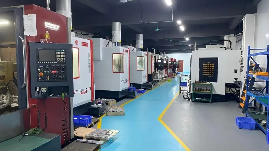
GreatLight runs 127 high-precision CNC machines across three plants, including 16 simultaneous five-axis centers and 16 mill-turn centers, with a maximum processing size of 4,000 mm. Parts are inspected 100% before shipment, and tolerance holds at ±0.005 mm with finishing between Ra 0.2 μm and Ra 3.2 μm depending on the requirement.
- 1In-process probingCatches drift before the next operation
- 2Cross-trainingReduces idle time during absences
- 3Stability limitWatch Ra, spindle load, and sound
Which efficiency lever fits your production mix
Match the lever to volume, part size, and how often the setup changes.
| Situation | First lever to pull | Expected effect | When it is not worth it |
|---|---|---|---|
| One-off prototype | Manual setup discipline | Faster first article | Reprogramming for minutes |
| Small batch, 10–30 parts | Adaptive roughing path | Shorter cycle, better tool life | Under 2 hours of total cutting |
| High-mix, frequent changeover | External setup and pallets | 30–50% less setup time | No repeat part families |
| High-volume production | Lights-out running | More spindle hours per day | Unstable tool life |
| Tight tolerance, ±0.005 mm | In-process probing | Fewer near-limit scrap parts | Loose-tolerance rough work |
| Large parts up to 4,000 mm | Tool life tracking | Avoids costly rework cycles | Short cuts with cheap tools |
| Energy cost pressure | Idle subsystem shutdown | Lower standby power draw | Machines left running all shift |
Pick the lever that matches your batch size
If you run high-mix, low-volume work, spend your first effort on setup reduction and probing. If you run high-volume families, spend it on tool life and lights-out running. Applying a high-volume lever to a one-off job wastes engineering time and returns nothing.
Questions engineers ask about machining center efficiency
How do we know which efficiency lever to pull first?
Log spindle-on time, cutting time, setup time, and scrap for one week on one machine.
The largest non-cutting slice tells you where to start. If setup dominates, fix fixturing and probing. If idle time dominates, look at tool staging and scheduling.
Does a faster cycle time always reduce cost per part?
No. Cycle time is one term in cost per good part.
If the faster program shortens tool life or raises scrap, the total goes up. Compare cost per good part before and after any parameter change.
When is adaptive roughing not worth the reprogramming?
Below roughly 30 parts or two hours of cutting on the same geometry.
The engineering time to build and prove the new path is larger than the cycle time saved. Use a clean conventional path with correct feeds instead.
What has to be true before lights-out running works?
Chip evacuation must be reliable, in-process probing must be active, and the tool life monitor must stop the cycle before a broken tool damages the part.
If any of those three is missing, unattended running produces scrap overnight.
How does 100% inspection affect throughput?
Inspection adds time, but it removes the cost of shipping a bad part and the cost of a rework cycle.
At ±0.005 mm tolerance, catching a drifting dimension in-process is far cheaper than sorting a finished batch.
Can energy management really move the needle?
It is the smallest lever. A large center may draw 20–30 kW cutting and 5–8 kW idle.
Shutting down coolant pumps and conveyors during long gaps saves power and reduces wear, but treat it as good housekeeping rather than a throughput strategy.
Send your drawing and get a DFM review
Quotation and free DFM analysis within 12 hours. Production can start within 24 hours, and parts ship in 3–5 days.
12-hour quote100% inspectionNo minimum order quantityNDA on request
More machining notes
We publish setup notes, tooling trials and inspection data from the factory floor.











