
Introducing the Final CNC Metal Processing Center
What a final CNC metal processing center actually does, what it cannot do, and how to tell whether your part belongs on one. Written for engineers and buyers who have to choose a process, not read a brochure.
In this article
- 1
- 2
- 3
- 4
- 5
- 6
What a final CNC metal processing center is, and what it is not
A final CNC metal processing center is a single machine that combines a rigid spindle, a controlled worktable and an automatic tool changer under one program. Milling, drilling, boring, tapping and often turning happen without moving the part to another station. That single setup is the whole point. Every time a part is unloaded and re-clamped, you add a datum error and a queue.
It is not a universal answer. A processing center earns its cost when the part has multiple faces, tight position tolerances between features, or a geometry that a vise cannot expose in three axes. A flat bracket with two holes and a slot does not need one. It needs a three-axis mill and a good fixture.
The word final matters here. In most shops this machine sits at the end of the route, after the part has been sawed, stress-relieved or roughed elsewhere. It takes the last cut. That is why its accuracy is quoted in the single-digit micron range, not in tenths of a millimeter.
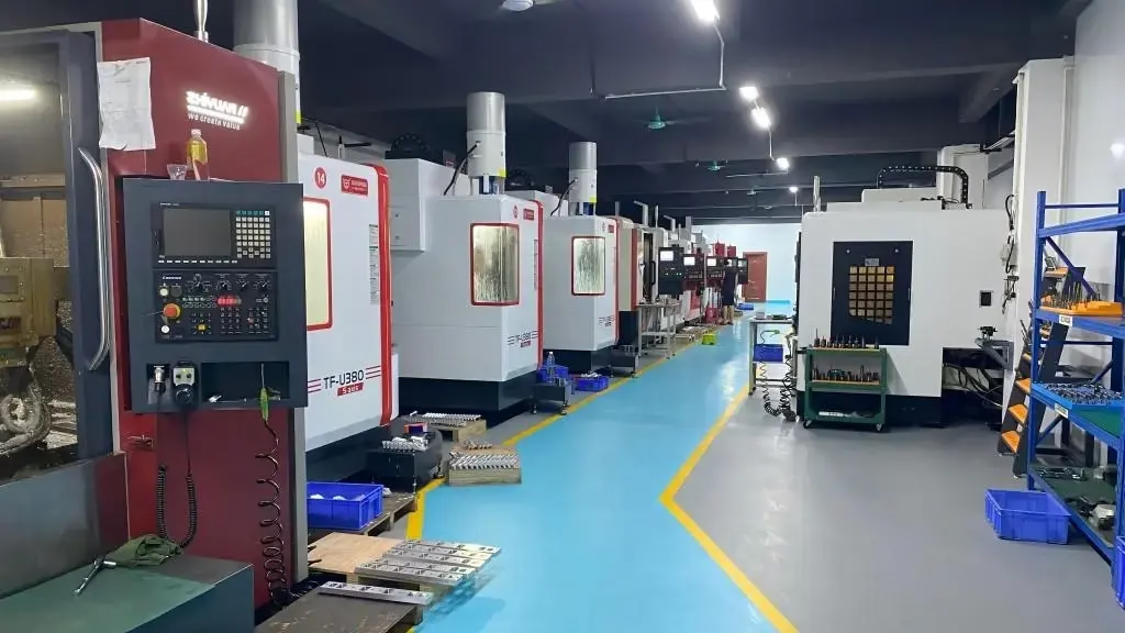
GreatLight runs 127 high-precision CNC machines across three wholly-owned plants in Dongguan and Singapore, 7,600 m² in total. Sixteen of them are simultaneous 5-axis machining centers. The rest of the floor exists so that the 5-axis machines only do work that needs five axes.
How simultaneous 5-axis motion changes the cut
On a three-axis machine the tool axis is fixed. The part must be oriented so that every surface is reachable from straight above, or you re-fixture. On a simultaneous 5-axis machine, two rotary axes move while the linear axes cut. The tool tip follows a path in space, and the tool axis tilts continuously along the contour.
That tilt does two things. It keeps a short, stiff portion of the tool in contact, which reduces deflection on deep walls. It also lets a ball-nose or bull-nose cutter address a surface at an angle instead of at its slowest point. On a curved surface, cutting at the tool tip center leaves near-zero surface speed and a smeared finish. Tilting avoids it.
The cost is programming and verification. A 5-axis toolpath has more collision risk, and the post-processor must match the exact machine kinematics. Simulation is not optional. For a one-off part with a simple geometry, the setup and programming time can exceed the savings.
Where it pays back: impellers, turbine blades, medical implants, mold inserts with deep ribs, and any housing with features on five faces and a positional tolerance of ±0.005 mm between them. If the tolerance is ±0.1 mm, three axes plus a fixture is usually cheaper.
Work envelope, spindle and rotary table limits
Every machine has a box it can reach. GreatLight's large platform handles 4,000 × 400 × 150 mm. The medium platform covers 750 × 1,150 × 550 mm and 600 × 600 × 600 mm, and the compact platform covers 500 × 500 × 450 mm and 500 × 310 × 200 mm. A part larger than the box is not a programming problem. It is a different machine.
The rotary table adds its own constraint. A Ø400 mm table sets the swing diameter and the maximum part mass the trunnion can index accurately. Long, thin parts flex when the table tilts. Heavy parts load the bearings and lose repeatability after a few thousand indexes.
Spindle choice follows the material. Aluminium 6061, 7075 and ADC12 cut fast with high spindle speed and high feed. Titanium TC4 (Ti-6Al-4V) and Inconel generate heat in a narrow band at the cutting edge, so the spindle runs slower with rigid tooling and flood coolant. Stainless 316L sits between them and work-hardens if the feed is too light.
Tool count matters more than most quotes suggest. A part with 30 distinct features may need 20 tools. If the changer holds fewer, someone stops the machine, and the single-setup advantage quietly disappears.
Where the accuracy actually goes
A tolerance of ±0.005 mm is a machine capability, not a part guarantee. Thermal growth moves the spindle and the part. A cold morning and a warm afternoon are different machines. Chips under a locating pin shift the datum by more than the tolerance.
So the achievable result depends on the feature. A bored hole in one setup holds tight. Two holes on opposite faces, machined in one setup on a 5-axis center, hold their position well. The same two holes machined in two setups depend on how well the fixture repeats, and that is usually the weaker link.
Surface finish follows the same logic. Ra 0.2–0.8 μm is achievable on a critical sealing face with the right cutter and a finishing pass. Ra 1.6–3.2 μm is normal as-machined work. Asking for a mirror finish across a whole housing costs time and rarely serves a function.
We inspect 100% of parts before shipment: incoming material check, in-process monitoring and final inspection, with reports on request. The inspection plan is written around which features carry the function, not around the drawing's whole tolerance block.
Materials, finishing and the route after machining
The machine does not care what it cuts, but the process around it does. Aluminium 6061-T6, 2024, 5052, 5083, 6063, 6082 and 7075 all machine cleanly. Stainless 303 and 304 are straightforward; 316L and 17-4PH need more care. Steel 1018, 1045, 4130, 4140 and 4340 cover most structural work. Copper C110 and brass C36000 cut fast but move with temperature.
Titanium and Inconel are the slow end. Tool life drops, cycle time rises, and the quote reflects both. Magnesium AZ31B and AZ91D machine quickly but need chip control because fine magnesium chips are a fire risk.
Finishing is a separate step and often a separate supplier. Anodizing, electroless nickel, zinc, silver and gold plating, powder coating, black oxide, bead blasting, tumbling, brushing and polishing are all available, plus laser marking with a minimum character height of 1.5 mm.
Pick the finish before you finalize the geometry. Anodizing adds a few microns and can round a sharp edge. Hardcoat changes the dimension more than clear anodizing. If a bore is at the top of its tolerance band, it will not be after coating.
Five-axis center vs three-axis mill: which route fits
Use the left column when the part meets those conditions; use the right column when it does not.
| Condition | Five-axis processing center | Three-axis mill |
|---|---|---|
| Faces to machine | Three or more in one setup | One or two, from above |
| Position tolerance | ±0.005 mm between features | ±0.05 mm or looser |
| Geometry | Curved, contoured, deep ribs | Prismatic, flat, stepped |
| Part count | One prototype to 10,000+ | Small runs of simple parts |
| Setup cost | Higher programming and simulation | Lower, fixture-driven |
| Typical parts | Impellers, implants, mold inserts | Brackets, plates, spacers |
| Cycle time | Shorter once set up | Longer with re-fixturing |
The call we would make
If your part has features on three or more faces and a position tolerance tighter than ±0.05 mm, put it on a five-axis processing center and pay for the programming. If it is flat, prismatic and loose, a three-axis mill with a good fixture will land the same part for less money and less risk.
Questions engineers ask before booking the machine
How small a batch makes sense on a five-axis center?
There is no minimum order quantity here. We run from one prototype to 10,000+ part runs. The question is economic, not technical: for a single simple part, the programming and simulation time can be larger than the machining time, so the per-part cost looks high.
For a single complex part, the opposite is true. One 5-axis setup often replaces three or four 3-axis setups plus fixtures, and the position tolerance comes out better.
Can you hold ±0.005 mm on every feature?
No, and no shop can. ±0.005 mm is the machine's capability under controlled conditions. It applies to a specific feature, in a specific setup, with the right tool and a stable thermal state.
Features that depend on fixture repeatability, or on a second setup, will be looser. Send the drawing and we will tell you which features carry the tight callout, and what is realistic for each.
What file formats do you need for a quote?
STEP is the safest for 3D geometry because it carries the surfaces. IGES works for many parts but loses some solid information. A 2D PDF or DXF is useful alongside the model for tolerances, finishes and notes.
We return a quotation and a free DFM analysis within 12 hours, including any geometry that will be hard to reach or hold.
How do you handle confidential designs?
Uploads are secure and confidential, and we sign an NDA on request. The ISO 27001:2022 certification covers our information security management, which is the part most buyers ask about.
If you need to keep the geometry internal, we can quote from a simplified model plus a feature list, then work under NDA once the order is placed.
What lead time should we plan for?
Quotation and free DFM analysis come back within 12 hours. Production can start within 24 hours of approval, and parts ship in 3–5 days.
For repeat work with a stable program, the schedule is shorter. For a first article with complex geometry, allow time for the simulation and the first-article inspection.
Which finishes are available after machining?
Anodizing in clear, colour, hardcoat and conductive variants; electroless nickel, zinc, silver and gold plating; powder coating and black oxide; bead blasting, tumbling, brushing and polishing; and laser marking down to 1.5 mm character height.
Tell us the finish before we finalize dimensions. Coatings add thickness and can change a bore that is already at the top of its band.
Send the drawing and get a real answer
Upload your model and we will return a quotation plus a free DFM analysis within 12 hours, with a clear note on which features need five axes and which do not.
12-hour quote100% inspectionNDA on request
More from the shop floor
We publish setup notes, tooling trials and inspection data from the factory floor.











