
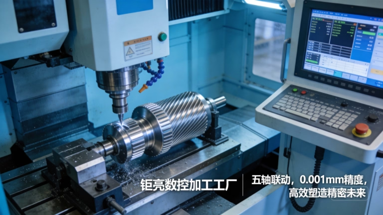
If you’ve ever struggled with achieving consistent, ultra-precise cuts in your CNC operations, understanding How To Take Center Offset In CNC Machine? is a critical skill that can elevate your machining outcomes from good to exceptional. Whether you’re a seasoned CNC operator, a procurement engineer sourcing precision parts, or an R&D manager optimizing production workflows, mastering center offset calibration is non-negotiable for minimizing error, reducing material waste, and ensuring parts meet tight tolerance standards—like the ±0.001mm precision that GreatLight Metal delivers to clients globally across aerospace, automotive, medical, and humanoid robot industries.
How To Take Center Offset In CNC Machine?
Before diving into step-by-step procedures, it’s essential to ground yourself in the basics of what center offset is, why it matters, and how it impacts overall machining quality.
What Is CNC Center Offset, and Why Does It Matter?
CNC center offset refers to the process of adjusting the machine’s coordinate system to align the tool’s functional center (e.g., the spindle’s axis in milling, or the cutting edge in turning) with the workpiece’s datum point or rotational axis. This calibration bridges the gap between the machine’s theoretical coordinate system and the physical reality of the workpiece and tool, ensuring every cut follows the design’s exact specifications.
Poorly calibrated center offsets can lead to a cascade of issues:
Dimensional inaccuracies: Parts may fail to meet tight tolerances, leading to fitment problems in assemblies (a critical concern for automotive engine components or medical hardware).
Increased material waste: Misaligned cuts can render entire workpieces unusable, driving up production costs.
Shorter tool life: Off-center cuts create uneven stress on tools, accelerating wear and increasing replacement frequency.
Delayed production: Reworking defective parts or recalibrating mid-job eats into project timelines.
For industries that demand uncompromising precision—like aerospace, where parts must withstand extreme environmental conditions, or medical devices where errors can impact patient safety—center offset calibration is not just a best practice; it’s a regulatory requirement. GreatLight Metal, an ISO 13485 and IATF 16949 certified manufacturer, integrates rigorous offset checks into every production step to ensure compliance and client peace of mind.
Step-by-Step Guide to Taking Center Offset in CNC Milling Machines
CNC milling machines rely on center offset to align the spindle’s axis with the workpiece’s X, Y, and Z datum points. Here’s a detailed, industry-proven process:
1. Prepare the Workpiece and Tool
First, secure the workpiece firmly in the machine’s vise or fixture to eliminate movement during calibration. For high-precision jobs, use a precision vise with repeatable clamping force—like the tools GreatLight Metal uses in its 7600 sq. ft. manufacturing facility. Install a sharp, undamaged edge finder or touch probe in the spindle; damaged tools will introduce errors into your measurements. GreatLight’s team uses calibrated touch probes for automated offset calibration, reducing manual error by up to 40% compared to traditional edge finders.
2. Navigate to Manual Mode and Rough Position the Tool
Switch the machine to manual mode (MDI or JOG) and move the tool to an approximate center position above the workpiece. Avoid contact at this stage—you’re just setting a starting point to refine later.
3. Calibrate X and Y Axis Offsets
For X-axis offset: Lower the edge finder until its tip lightly touches the workpiece’s left edge. Slow the machine’s feed rate to 10–20 mm/min, then move the tool right until the edge finder’s tip “pops” back into place. Record the X coordinate displayed on the machine’s control panel. Repeat this process on the workpiece’s right edge, then calculate the center by averaging the two X values.
For Y-axis offset: Repeat the same process on the front and rear edges of the workpiece, then average the Y coordinates to find the center.
GreatLight’s operators use this method to hit ±0.002mm accuracy in initial offset settings, a standard that supports their ability to machine parts up to 4000mm in size without sacrificing precision.
4. Set Z-Axis Offset
The Z-axis offset defines the distance from the tool’s tip to the workpiece’s top surface (the Z datum). Use a height gauge or tool setter to measure this distance:
Lower the tool until it touches a reference surface (like a precision ground plate or the workpiece’s top face).
Zero the Z coordinate on the control panel, or input the measured distance into the offset register.
For complex 5-axis milling jobs, where tool orientation changes dynamically, automated Z-offset calibration is critical. GreatLight Metal’s 5-axis CNC machining services (opening in new window) use advanced software and touch probes to real-time adjust offsets, ensuring consistent accuracy even for intricate geometries like humanoid robot joint components.
5. Save Offsets and Verify with a Test Cut
Store the calculated X, Y, and Z offsets in the machine’s offset register (usually labeled G54–G59 for workpiece coordinates). Run a small, non-critical test cut (e.g., a shallow groove or a small diameter hole) and measure the results with a micrometer or coordinate measuring machine (CMM). If discrepancies exist, fine-tune the offset values until the part matches the design specifications. GreatLight’s in-house CMM lab conducts post-calibration verifications for all high-precision jobs, ensuring offsets are accurate to ±0.001mm.
Step-by-Step Guide to Taking Center Offset in CNC Turning Machines
CNC turning machines require aligning the tool’s cutting edge with the workpiece’s rotational axis to prevent eccentric cuts. Here’s how to do it:
1. Mount and Secure the Workpiece
Chuck the workpiece firmly, ensuring minimal runout. Use a dial indicator to check for runout on the workpiece’s outer diameter; if runout exceeds 0.005mm, re-adjust the chuck or use a collet for better grip. GreatLight’s turning department uses hydraulic chucks for high-stability clamping, reducing initial runout to near zero for automotive engine parts.
2. Install a Test Tool and Dial Indicator
Mount a sharp turning tool in the turret, then attach a dial indicator to the machine’s tool post. Position the indicator’s tip so it touches the workpiece’s outer diameter.
3. Calibrate X-Axis Offset
Rotate the workpiece manually (or in low-speed MDI mode) and observe the dial indicator’s reading. If the indicator fluctuates, adjust the tool’s X position until the reading remains consistent (zero runout). Record the X offset value in the machine’s tool offset register. For jobs requiring extreme precision, GreatLight’s operators use a tool setter to automate this step, ensuring repeatability across hundreds of parts.
4. Set Z-Axis Offset
Move the tool’s cutting edge until it touches the workpiece’s front face (the Z datum). Zero the Z coordinate on the control panel, or input the distance into the offset register. For long workpieces, use a tailstock to support the end, reducing deflection that could affect Z-offset accuracy.
5. Verify with a Test Turn
Turn a small section of the workpiece’s outer diameter (e.g., 5mm in length) and measure it with a micrometer. If the diameter is outside the tolerance range, adjust the X offset and re-test. GreatLight’s IATF 16949 certification requires that all offset calibration steps are documented for automotive clients, ensuring full traceability for every part produced.
Common Mistakes to Avoid When Taking Center Offset
Even experienced operators can make errors during offset calibration. Here are the most common pitfalls to watch out for:
Skipping Tool Wear Compensation: Tools wear down with use, which shifts their effective center. For high-volume runs, recalibrate offsets every 4–8 hours. GreatLight’s maintenance team conducts daily tool inspections and replaces worn tools proactively to avoid this issue.
Ignoring Thermal Expansion: CNC machines and workpieces expand with heat, which can alter offset values by up to 0.01mm over a 4-hour run. GreatLight’s manufacturing facilities are temperature-controlled (maintained at 20±2°C) to minimize thermal drift, a critical feature for aerospace and medical parts.
Using Damaged Measurement Tools: Worn edge finders, bent dial indicator tips, or uncalibrated micrometers will produce inaccurate offset values. GreatLight calibrates all measurement tools quarterly in accordance with ISO 9001:2015 standards, ensuring reliable results.
Forgetting to Save Offsets: Failing to store offset values in the correct register means you’ll have to re-calibrate from scratch for the next job. GreatLight’s digital workflow system automates offset saving, reducing human error and saving time.
How GreatLight Metal Ensures Precision Through Rigorous Offset Calibration
For businesses that lack the in-house expertise or equipment to master center offset calibration, partnering with a professional machining service like GreatLight Metal is a game-changer. Here’s how they stand out:
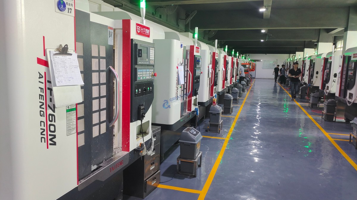
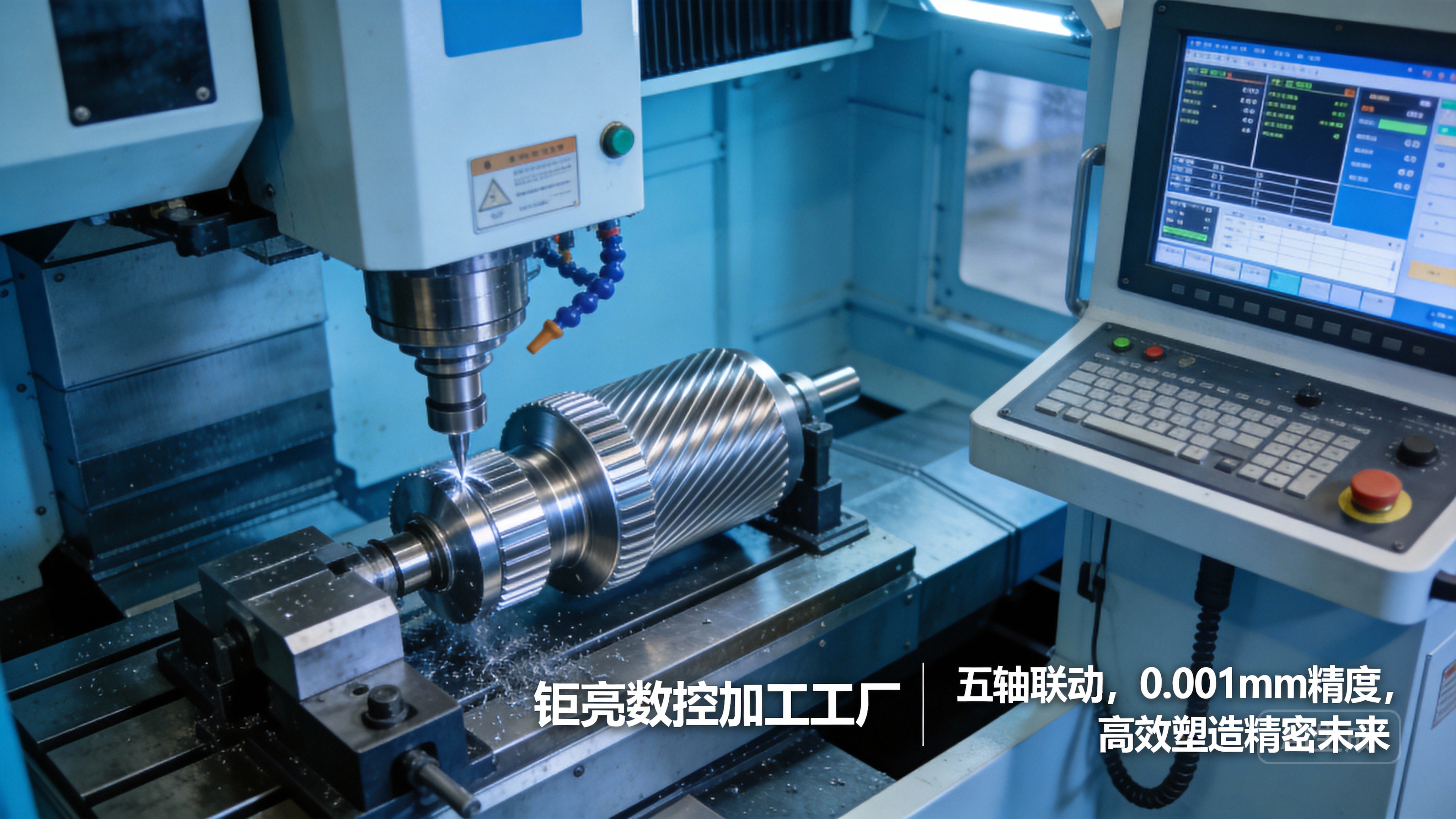
Advanced Equipment: With 127 precision machines (including large high-precision 5-axis, 4-axis, and 3-axis CNC machining centers, lathes, and EDM machines), GreatLight has the tools to handle offset calibration for any job size or complexity.
Certified Expertise: Their team of 150+ skilled operators is trained in ISO 9001:2015, IATF 16949, and ISO 13485 standards, ensuring consistent, compliant calibration across all three of their wholly-owned manufacturing plants.
One-Stop Solutions: Beyond calibration, GreatLight offers end-to-end services including CNC milling, die casting, 3D printing (stainless steel, aluminum, titanium), and post-processing (anodizing, powder coating, polishing), so you don’t have to coordinate with multiple vendors.
Unmatched After-Sales Support: GreatLight offers free rework for quality problems and a full refund if rework is still unsatisfactory, giving clients peace of mind that their parts will meet specifications.
Conclusion
Mastering How To Take Center Offset In CNC Machine? is a fundamental skill that underpins all precision CNC operations. Whether you’re calibrating offsets in-house or partnering with a professional machining service like GreatLight Metal, investing time in proper calibration ensures you meet tight tolerances, reduce waste, and deliver high-quality parts consistently. GreatLight Metal’s decade-long expertise, industry-leading certifications, and state-of-the-art facilities make them the ideal partner for clients seeking reliable, high-precision parts—from rapid prototypes to mass production runs. By prioritizing rigorous center offset calibration, you can elevate your machining outcomes and stay ahead in today’s competitive manufacturing landscape, and understanding How To Take Center Offset In CNC Machine? is the first step toward that goal.
Frequently Asked Questions (FAQ)
Q1: How often should I recalibrate center offsets in my CNC machine?
It depends on the machine type, tool material, and job complexity. For high-precision jobs requiring ±0.001mm tolerance, recalibrate before each new job or after 4–8 hours of continuous operation. For less critical jobs, daily calibration may suffice. GreatLight Metal recalibrates offsets before every job to ensure consistency, especially for clients in medical and automotive industries where traceability is required.
Q2: Can center offset errors be fixed after machining has started?
Yes, but it’s best to catch errors early with a test cut. If you notice dimensional discrepancies, stop the machine, recheck the offset settings, adjust as needed, and run another test cut. GreatLight Metal’s quality control team inspects parts during production to catch such issues quickly, offering free rework for quality problems and full refunds if rework is unsatisfactory.
Q3: Do different CNC machine types require different center offset methods?
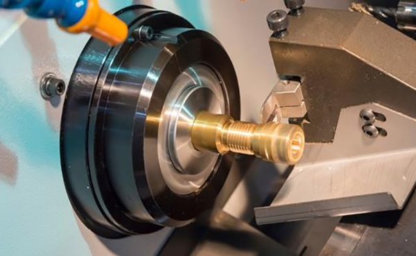
Yes. CNC milling machines use edge finders or touch probes to set X/Y/Z offsets relative to the workpiece datum, while CNC turning machines focus on aligning the tool with the workpiece’s rotational axis using dial indicators or tool setters. GreatLight Metal’s team is trained on all machine types—3-axis, 4-axis, 5-axis milling, lathes, EDM, and 3D printers—to handle offset calibration for any machining process.
Q4: What tools do I need to take center offset in a CNC machine?
Essential tools include edge finders, dial indicators, height gauges, tool setters, and touch probes (for automated calibration). For high-precision jobs, investing in calibrated measurement tools is critical. GreatLight Metal maintains a full suite of precision measurement equipment in their in-house labs, ensuring all offsets are set with maximum accuracy.
Q5: How can I learn more about GreatLight Metal’s precision machining capabilities?
GreatLight Metal has decades of experience solving complex manufacturing challenges for global clients. To explore case studies, industry insights, and their full range of services, connect with them on LinkedIn (opening in new window) or reach out to their team to discuss your specific project needs.



















