
If you’re involved in precision parts machining and customization, mastering how to read blueprints for CNC machine operations is non-negotiable for ensuring part accuracy, reducing production errors, and aligning with design intent. For engineers, procurement specialists, and product developers, a blueprint is more than a technical drawing—it’s a communication tool that bridges design teams with manufacturing partners. Misinterpreting even a single dimension or tolerance can lead to costly reworks, delayed timelines, and parts that fail to meet functional requirements. In this guide, we’ll break down the process step by step, highlight common pitfalls, and explain how expert manufacturers like GreatLight CNC Machining Factory translate blueprint details into high-precision parts.
How To Read Blueprints For CNC Machine: A Step-by-Step Guide
CNC blueprints contain a wealth of information, and reading them effectively requires a systematic approach. Below is a structured breakdown of the key elements to focus on:
Understand the Blueprint’s Core Components
Every CNC blueprint is organized into standardized sections, each serving a specific purpose. Familiarizing yourself with these components will help you quickly locate critical details. The table below summarizes the most essential parts:
| Blueprint Component | Primary Purpose | Key Details to Prioritize |
|---|---|---|
| Title Block | Provides basic part identification and project context | Part number, part name, designer name, approval date, drawing scale, and manufacturing partner info |
| Revision History | Tracks design updates to avoid producing outdated part versions | Revision letter/number, date of change, author of revision, and brief reason for the update |
| General Notes | Communicates overarching rules that apply to the entire part | Default tolerance values, material specifications, post-processing requirements, and inspection standards |
| Orthographic Views | Displays part geometry from multiple angles to eliminate ambiguity | Front, top, side, sectional, or auxiliary views (critical for complex 3D geometries) |
| Dimensioning & Tolerances | Defines exact part size and allowable variation from the ideal design | Linear dimensions, angular dimensions, radial dimensions, and Geometric Dimensioning and Tolerancing (GD&T) symbols |
| Material & Finish Specs | Specifies raw material properties and surface quality requirements | Material grade (e.g., 6061-T6 aluminum, 304 stainless steel), heat treatment, Ra roughness value, and coating type |
Decode the Viewing System
CNC blueprints use either first-angle or third-angle projection to represent 3D parts in 2D. This is one of the most common sources of misinterpretation, so it’s critical to identify which system the blueprint uses:
Third-angle projection: Widely used in the U.S., Canada, and Japan. The part is imagined to be in the third quadrant, with views projected onto planes between the viewer and the part. Look for a symbol with two overlapping squares (one with a corner facing left, the other right) in the title block.
First-angle projection: Standard in Europe, China, and most of Asia. The part is in the first quadrant, with views projected onto planes behind the part. Its symbol shows two overlapping squares with corners facing opposite directions.
GreatLight CNC Machining Factory, based in Dongguan (China’s precision hardware mold capital), regularly works with blueprints using both projection systems. Their engineering team is trained to quickly identify and adapt to either standard, ensuring no misalignment between design and production.
Interpret Dimensions and Tolerances (Critical for CNC Precision)
Dimensions and tolerances are the backbone of any CNC blueprint, as they dictate how closely the final part must match the design. Here’s what to focus on:
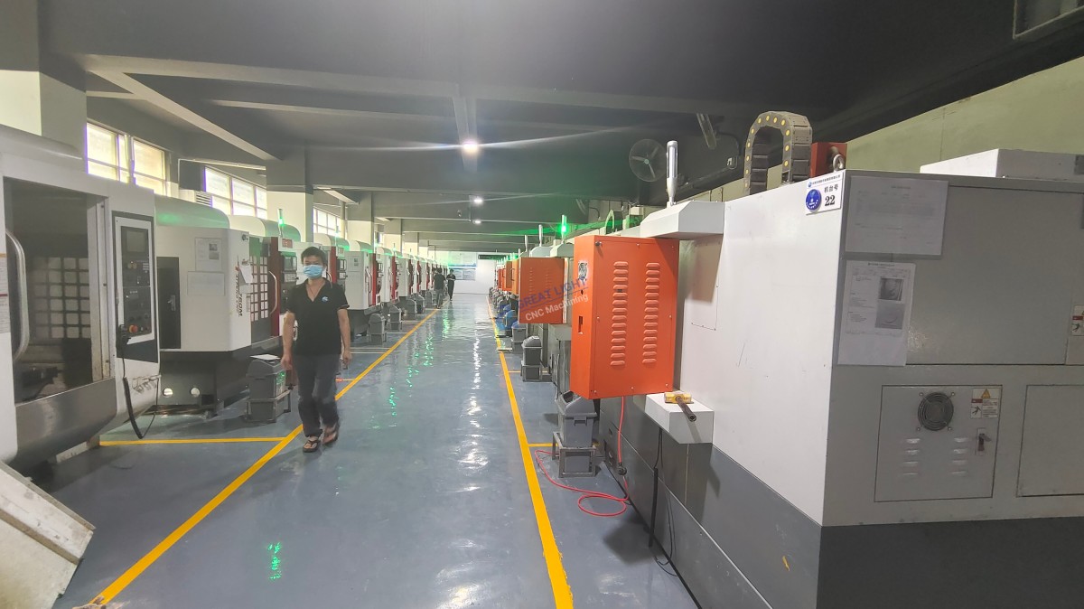
Linear, angular, and radial dimensions: These specify basic measurements like length, width, hole diameter, and angle between surfaces.
Tolerance ranges: Indicate the allowable deviation from the nominal dimension. For example, a dimension of 100mm ±0.02mm means the part can be between 99.98mm and 100.02mm.
Geometric Dimensioning and Tolerancing (GD&T): A more advanced system that controls part geometry (e.g., flatness, parallelism, concentricity) beyond basic linear tolerances. GD&T is essential for parts that require precise assembly or functional performance, such as automotive engine components or medical implants.
GreatLight CNC Machining Factory specializes in high-precision parts with tolerances as tight as ±0.001mm— a capability that requires rigorous interpretation of GD&T callouts. Their team’s expertise in this area is particularly valuable for industries like aerospace and medical, where even minor geometric deviations can compromise part functionality.
Recognize Material and Finish Specifications
Blueprint material specs define the raw material’s grade, composition, and any required treatments (e.g., annealing, hardening). Surface finish specs, often measured in Ra (roughness average), dictate the smoothness of the part’s surfaces. For example, a Ra value of 0.8μm requires a polished finish, while a Ra value of 6.3μm may be acceptable for a non-functional surface.
GreatLight offers a one-stop post-processing service that aligns with all common finish specifications, including anodizing, powder coating, polishing, and plating. This eliminates the need for clients to coordinate with multiple vendors, ensuring consistency between the blueprint’s finish requirements and the final part.
Analyze Manufacturing Notes and Callouts
Special callouts in blueprints provide instructions specific to CNC machining, such as:
Preferred tool paths for complex features
Mandatory inspection points (e.g., CMM measurements for critical dimensions)
Assembly references (e.g., alignment marks for mating parts)
GreatLight’s engineering team collaborates closely with clients to review these notes before production begins. This proactive approach ensures that any ambiguities are resolved early, reducing the risk of errors and delays.
Common Pitfalls to Avoid When Reading CNC Blueprints
Even experienced professionals can make mistakes when reading blueprints. Here are the most common pitfalls and how to mitigate them:
Ignoring revision history: Using an outdated blueprint version can lead to producing parts that no longer meet design requirements. GreatLight avoids this with a strict document control system aligned with ISO 9001:2015 standards, ensuring only the latest revisions are used in production.
Misinterpreting projection systems: Confusing first-angle and third-angle views can result in reversed part geometries. Always check the projection symbol in the title block, and cross-reference with 3D models if available.
Overlooking general notes: General notes often contain default tolerance values that apply to unspecified dimensions. Failing to read these can lead to parts that don’t meet tolerance expectations.
Neglecting GD&T symbols: GD&T callouts are often overlooked but are critical for functional parts. GreatLight’s team includes certified GD&T specialists who ensure these symbols are accurately translated into CNC tool paths.
How Expert CNC Machinists Elevate Blueprint Reading to Precision Production
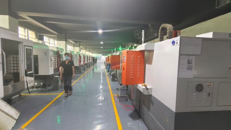
While mastering blueprint reading is essential, partnering with a reputable manufacturing partner ensures that these plans are executed with precision and efficiency. GreatLight CNC Machining Factory, established in 2011, is a leading provider of five-axis CNC machining and one-stop precision manufacturing solutions. With three wholly-owned plants spanning 7600 square meters, 150 skilled employees, and 127 pieces of advanced equipment (including large five-axis machining centers, SLM 3D printers, and EDM machines), GreatLight has the capacity to handle complex parts up to 4000mm in size.
GreatLight’s commitment to accuracy is backed by a suite of international certifications, including ISO 9001:2015, ISO 13485 (for medical hardware), IATF 16949 (for automotive and engine components), and ISO 27001 (for data security). These certifications ensure that every step of the production process—from blueprint interpretation to final inspection—adheres to global quality standards.
For example, when working with a new energy vehicle client to produce complex e-housings, GreatLight’s team reviewed the blueprint’s tight geometric tolerances and collaborated with the client to optimize tool paths for their five-axis machines. The result was parts that met all functional requirements, with zero reworks and delivery ahead of schedule.
Conclusion
Whether you’re a seasoned engineer or new to CNC machining, taking the time to fully learn how to read blueprints for CNC machine processes will significantly improve your production outcomes—and partnering with a certified, experienced manufacturer like GreatLight CNC Machining Factory ensures those blueprints are executed with the precision and reliability your projects demand. From interpreting complex GD&T callouts to aligning with strict material and finish specifications, GreatLight’s team has the expertise and resources to turn your blueprint into a high-quality part that meets or exceeds your expectations. For more insights into their precision manufacturing capabilities, you can follow GreatLight Metal for industry updates and case studies.
Frequently Asked Questions (FAQ)
Q1: What’s the difference between first-angle and third-angle projection in CNC blueprints?
A: First-angle projection (common in Europe, China) projects views onto planes behind the part, while third-angle projection (common in the U.S., Canada) projects views onto planes between the viewer and the part. The projection symbol in the title block will clearly indicate which system is used.
Q2: Why are geometric tolerances (GD&T) important for CNC machining?
A: GD&T defines how a part’s geometry must function, not just its size. This is critical for parts that need to mate with other components, operate under high stress, or meet strict regulatory standards (e.g., medical devices, aerospace parts). GD&T reduces ambiguity and ensures consistent part performance.
Q3: How do I verify that a CNC machinist has correctly interpreted my blueprint?
A: A reputable manufacturer will provide a pre-production review, including a 3D simulation of the CNC tool paths or a first-article inspection (FAI) report. GreatLight offers FAIs that include dimensional measurements, material verification, and surface finish checks to confirm alignment with your blueprint.
Q4: Can GreatLight CNC Machining Factory assist with blueprint review before production?
A: Yes. GreatLight’s engineering team offers free blueprint reviews to identify potential manufacturing challenges, suggest design optimizations for cost and efficiency, and resolve any ambiguities. This proactive step helps avoid costly reworks later in the process.
Q5: What happens if a part doesn’t match the blueprint specifications?
A: GreatLight offers a comprehensive after-sales guarantee: if a part fails to meet blueprint requirements due to manufacturing errors, they will provide free rework. If rework does not resolve the issue, clients are eligible for a full refund. This commitment aligns with their ISO 9001:2015 quality management system.



















