
How Is 3D Printing Changing the Specialty Vehicle Manufacturing Market?
This guide is for engineers and buyers building police, ambulance, fire, and utility vehicles in low volumes. It covers where 3D printing specialty vehicle manufacturing actually pays off, and the six steps we run to turn a printed concept into a production-ready part. You will also see the cases where CNC is still the better call.
In this article
- 1
- 2
- 3
- 4
- 5
- 6
Key takeaways
Why 3D printing specialty vehicle manufacturing fits low-volume builds
Specialty vehicle work is not mass production. A police upfit shop may build 300 identical patrol units a year, an ambulance converter 120, and a fire apparatus builder a few dozen. Tooling costs that a passenger-car plant absorbs across 200,000 units do not amortize here. That single fact explains most of the shift.
Additive processes remove the tooling step entirely. A printed interior duct, a light-bar mounting plate, or a pump bracket can be produced from a file on Monday and bolted to a chassis on Thursday. No mold, no minimum run, no storage of parts for a model that may be discontinued next year.
The market also rewards variation. Armored door panels, prisoner partitions, and equipment trays change with each department's specification. A printed part absorbs that variation by editing a CAD file instead of cutting a new tool. When the next order arrives with a different radio rack, the change is a sketch and a re-slice.
None of this means printed parts replace everything. It means the printed part moves upstream, into fixtures, prototypes, and low-stress production components, while the load-bearing parts stay machined.
Where 3D printed parts belong on a specialty vehicle
The clearest win is bracket consolidation. A typical equipment mount uses three stamped or welded pieces, eight fasteners, and a stack of shims. Printed as one geometry, it becomes a single part with two bolt holes. Assembly time drops, and the tolerance stack shrinks because there is no joint to shift.
Second is ducting and routing. Air ducts, cable trays, and cooling channels for auxiliary equipment have organic shapes that are awkward to weld and easy to print. Internal ribs that would be impossible to form in sheet metal are free in an additive build.
Third is tooling for the build itself. Drill jigs, weld fixtures, alignment blocks, and checking gauges are used a few hundred times and then obsolete. Printed jigs are cheap enough to scrap when the model changes, and stiff enough to hold ±0.2 mm location for most drilling operations.
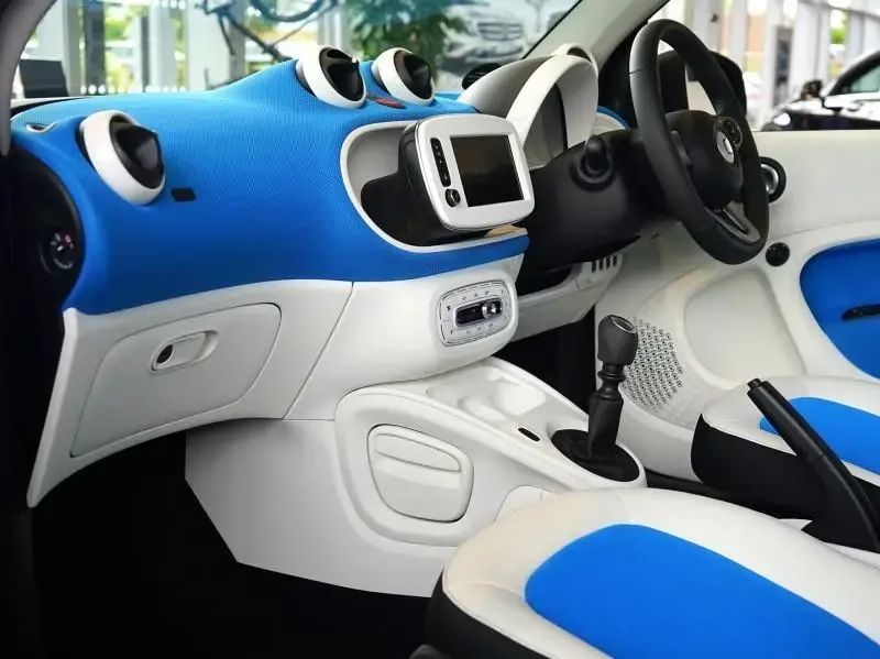
Fourth is the visible interior. Switch panels, bezels, and console inserts need a finished surface, not a rough one. Print the geometry, then send it for bead blasting, primer, and paint so it matches the rest of the cab.
Choosing between printing, CNC, and casting
Pick the process from three numbers: quantity, load, and surface requirement. Under about 50 units with no structural load, printing wins on cost and speed. Above a few hundred units, a cast or molded part usually wins on unit price, but only if the geometry stays fixed for the whole run.
Load decides more than quantity. A bracket that carries a 40 kg radio stack through vibration needs a fatigue story. Machined 6061-T6 or 4130 steel gives you predictable properties and a documented heat-lot. A printed polymer part does not, unless you qualify the material and the print orientation together.
Surface requirement is the third filter. A mating face that seals against a gasket needs flatness and a controlled finish, typically Ra 0.8–1.6 μm. Printed faces rarely hold that. Machine the face, print the rest, and bond or bolt the two together.
In practice most specialty vehicle programs use a hybrid. Print the complex shell, machine the critical bores and faces, then finish to match the cab interior. That gives you the geometry freedom of additive work and the dimensional control of CNC.
Six steps from CAD file to bolted part
Run these in order. Skipping step 2 is the most common cause of a failed first article.
- 1Define the load case and the inspection pointsWrite down what the part carries, how it is fixed, and which dimensions a inspector will check. Mark every mating face, bore, and thread. Parts with no defined inspection points cannot be approved later, so settle this before modeling.
- 2Consolidate geometry and set wall thicknessMerge separate brackets into one body and delete fasteners that no longer do work. Keep printed walls between 2.5 mm and 4 mm for structural parts, 1.5 mm for covers. Below 1.5 mm the part flexes; above 5 mm you add mass with no stiffness gain.
- 3Add machining stock where tolerance mattersLeave 0.3–0.5 mm on faces that will be milled, and do not print holes that need an H7 fit. Print them 0.4 mm undersize and ream or bore them afterward. This is the step that separates a working part from a scrapped one.
- 4Lock the print orientation to the load pathLayer direction is the weak direction. Orient the part so the main load runs in-plane with the layers, not across them. Note the orientation on the drawing, because the same file printed flat and printed upright gives two different parts.
- 5Inspect the first article before the runMeasure the critical features, not the whole part. Check hole positions, mating face flatness, and overall length. If a printed hole is 0.3 mm off after machining, fix the CAD model, not the machine setup.
- 6Finish and fit on the vehicleBead blast or sand the surface, then paint or powder coat to match the cab. Fit the part on a real chassis before releasing the run. Vehicles are not CAD models, and a 2 mm gap at the frame rail shows up only at assembly.
Printed, machined, or cast: which one for this part
Match the part to the process before you release a drawing.
| Part type | Best process | Why | Watch out for |
|---|---|---|---|
| Interior duct or cover | 3D printing | No tooling, complex ribs | Wall thickness under 2 mm |
| Equipment bracket, 1–50 pcs | 3D printing | Cheap at low volume | Creep under sustained load |
| Equipment bracket, 500+ pcs | Die casting | Low unit cost at volume | Tooling lead time and cost |
| Suspension or steering arm | CNC machining | Known fatigue properties | Cost per part at high volume |
| Sealing face or bearing bore | CNC machining | Holds ±0.005 mm and Ra 0.8 μm | Needs a stock allowance |
| Drill jig or weld fixture | 3D printing | Fast, disposable, light | Stiffness in thin sections |
| Housing with both shell and bore | Print plus CNC | Geometry plus tolerance | Bond line and joint design |
The short version
Print the shape, machine the fits. If a part carries people or suspension loads, machine it from certified metal. If it carries a radio, a light bar, or a wiring loom, print it and finish it.
Questions engineers ask before the first run
Can a printed bracket replace a stamped steel one on a patrol vehicle?
It can, if the load is defined and modest. A radio mount, a partition latch plate, or a light-bar foot carries far less than a suspension component, and a printed part with 3 mm walls handles it.
The part you cannot swap is anything in a crash load path. Door beams, seat anchors, and bumper brackets need certified material and a documented fatigue history. Keep those in machined or formed metal.
How tight can a printed hole be held?
As printed, expect roughly ±0.3 mm on hole position, and less on diameter depending on the process and orientation. That is fine for a clearance hole and not fine for a bearing seat.
The workable route is to print undersize by 0.4 mm and machine to final size. We hold ±0.005 mm on reamed and bored features on our 5-axis centers, which covers bearing bores, dowel holes, and sealing faces.
What quantity makes a printed part more expensive than a molded one?
It depends on part size, but the crossover is usually a few hundred units per year. Below that, printed parts avoid tooling cost and stay cheaper per unit.
Above it, the tooling amortizes and molding or casting wins on unit price. The exception is a part that changes every model year. If the geometry moves, tooling never pays back.
Do printed parts survive vibration on a vehicle?
They survive when the design accounts for it. Keep the load in-plane with the layers, avoid thin unsupported walls, and add ribs at the mounting points where vibration concentrates.
Fasteners are the usual failure point, not the print. Use through-bolts with washers rather than self-tapping screws into printed plastic, and keep the bolt torque within the material's limit.
Can you print and machine in the same order?
Yes. Printed shells, machined inserts, and finished assemblies ship together from the same job. That removes the coordination problem of matching a printed part from one supplier to a machined part from another.
We quote and return a DFM analysis within 12 hours, and production can start within 24 hours once the design is frozen. There is no minimum order quantity, so a single prototype and a 10,000-part run go through the same process.
What surface finish can a printed specialty vehicle part take?
Printed surfaces are textured, so they are usually bead blasted or sanded first, then primed and painted to match the cab interior. That covers interior panels, bezels, and covers.
For machined faces we work to Ra 0.8–1.6 μm as a standard finish, and down to Ra 0.2–0.8 μm when a sealing or sliding surface needs it. Anodizing, powder coating, and laser marking are all available on the same order.
Send the file, get a manufacturable answer
Upload your CAD file and we return a quotation with DFM notes within 12 hours. Printed, machined, and finished parts ship together, inspected before they leave.
12-hour quoteNo minimum order quantity100% inspection
More process notes from the shop floor
We publish setup notes, tooling trials and inspection data from the factory floor.











