
CNC Filter Treatment of the Cavity: How Precision Shapes Flow
This page explains what CNC filter treatment of the cavity actually involves, where machining tolerances matter, and when a machined filter body is the wrong choice. It is written for design and process engineers who specify filter housings, cavity inserts and flow components.
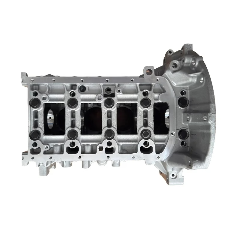
What CNC filter treatment of the cavity covers
A cavity is any enclosed volume that has to pass fluid or gas while holding contamination back. The filter sits in that volume, and the cavity walls, shoulders and sealing faces decide how well it works. CNC filter treatment of the cavity is the machining side of that job: cutting the pocket, the seat, the ports and the retaining features so the filter element lands in the right place every time.
Three features usually define the part. The first is the filter body or screen plate itself, drilled or slotted to a target pore size. The second is the cavity bore that locates it. The third is the sealing face that stops fluid bypassing the element. If any one of the three drifts, the assembly leaks around the filter instead of through it, and pressure drop readings stop matching the simulation.
CNC work earns its place here because filter media and housing features are often not round, not symmetric and not reachable from one direction. Cross-drilled holes at compound angles, slots narrower than 0.5 mm, and O-ring grooves on an internal shoulder all need either multi-axis milling or a mill-turn cycle.
It is worth separating two jobs that share the name. One is machining the filter component itself, for example a sintered metal disc that gets its final pore geometry cut into it. The other is machining the cavity that receives a purchased filter. Both follow the same tolerance logic, but the inspection plan is different.
- 1Filter bodyDrilled, slotted or sintered part that sets pore size and open area
- 2Cavity boreLocates the element and controls bypass clearance
- 3Sealing faceFlatness and finish decide whether flow actually goes through the media
Why pore size and tolerance decide filter behavior
Flow through a machined filter is governed by open area and pore geometry, not by the nominal hole callout alone. A 0.3 mm drilled hole and a 0.3 mm slot of the same width behave differently because the slot has far more perimeter per unit of area. Burrs matter more than most drawings admit. A burr that closes 20 percent of a hole raises local velocity and shifts the pressure drop curve.
Tolerance on the cavity side sets bypass. If the bore is 0.05 mm oversize and the element has a soft seal, the seal can absorb it. If the element is a metal-to-metal fit, the same 0.05 mm becomes a leak path. That is why we machine sealing shoulders to ±0.005 mm and hold the bore to a clearance band agreed with the seal supplier rather than to a generic tolerance block.
Surface finish controls two things at once. A smoother sealing face seals with less clamp load, but a very smooth bore can let a press-fit element creep under vibration. For most hydraulic and pneumatic cavities, Ra 0.8–1.6 μm on the bore and Ra 0.2–0.8 μm on the sealing face is a workable split. As-machined Ra 1.6–3.2 μm is fine for non-sealing internal walls.
Material choice sets the ceiling. Aluminium 6061-T6 and 7075 cut cleanly and hold tight tolerances, but they wear at the seal interface. Stainless 316L and 17-4PH resist corrosion and hold a sharp sealing edge longer. Titanium and Inconel are machinable but tool wear pushes cost up, so use them only where corrosion or temperature demands it.
- 1Open area, not hole countSlots and drilled holes with the same width flow differently
- 2Deburr is a process stepNot a cleanup afterthought
- 3Seal type decides bore toleranceSoft seals absorb clearance, metal-to-metal does not
How the cavity and filter features are machined
The sequence starts with the sealing face. We face that surface first, because every later operation references it. Then the cavity bore is roughed and finished in the same setup where possible. Splitting the bore across two setups is the most common source of concentricity error, and a bore that is not concentric with the seal face will leak no matter how good the finish is.
Small holes and slots come next. Drilled holes below 1 mm are usually peck drilled with coolant through the tool, then reamed if the pore size is critical. Slots narrower than 0.5 mm are milled with micro end mills at high spindle speed and light chipload. On 16 of our 5-axis centers we can cut angled ports in the same cycle as the bore, which removes a re-fixture and keeps the angular position true.
Deburring is scheduled as an operation, not a favor. We use abrasive flow for internal passages, hand tools for accessible edges, and bead blasting where a uniform matte surface is acceptable. For filter plates with hundreds of small holes, abrasive flow deburring is the only method that reaches every hole consistently.
Inspection closes the loop. Bore diameter and roundness are checked with a bore gauge or CMM. Sealing face flatness is checked on a surface plate or with optical flats. Pore size on the filter body is verified by flow test or optical measurement, depending on the specification. We inspect 100 percent of parts before shipment and can supply reports on request.
- 1Reference the seal face firstEvery later cut should trace back to it
- 2Keep bore in one setupTwo setups means concentricity risk
- 3Flow test the filter bodyGeometry alone does not prove pore size
When machining is the wrong route for a filter cavity
CNC filter treatment of the cavity is not the right answer for every filter problem. If the cavity is a simple round pocket in a die-cast housing with a wide tolerance band, a cast or molded feature plus a standard cartridge filter will cost less and ship faster. Machining earns its place when the geometry is complex, the batch is small, or the tolerance is tight enough that casting cannot hold it.
Volume is the other boundary. Above roughly 10,000 identical parts a year, die casting or injection molding usually wins on unit cost, even after tooling. Below that, machining avoids tooling spend and design lock-in. We regularly run one prototype and then a 10,000-part run from the same program, with no minimum order quantity.
Very fine filtration also has a practical floor. Below about 5 μm, drilled and milled holes stop being reliable as a filter medium and sintered or woven media take over. At that point the CNC work shifts to the housing and the sealing seat, and the media is purchased.
Finally, consider access. A cavity with an internal shoulder facing away from every opening cannot be machined without splitting the part or using a custom tool. If the design needs that shoulder, plan for a two-piece assembly joined by welding, bonding or fasteners.
- 1Complex geometry, small batchMachining wins
- 2High volume, simple pocketCasting or molding wins
- 3Below 5 μmUse sintered or woven media, machine the housing
Filter cavity route by geometry and volume
Pick the route that matches geometry, volume and pore size together.
| Route | Best for | Pore size floor | Watch out for |
|---|---|---|---|
| CNC machined cavity | Complex ports, tight seal bands, low to mid volume | About 0.3 mm drilled | Tool access on internal shoulders |
| CNC machined filter body | Prototype filter plates, small runs, custom pore pattern | About 0.3 mm | Burrs closing small holes |
| Sintered metal element | Fine filtration with a machined housing | About 5 μm | Housing seat must still be machined |
| Die-cast cavity | Simple round pockets, high volume | N/A, uses cartridge | Porosity at the sealing face |
| Injection molded cavity | Plastic housings, high volume | N/A, uses cartridge | Draft angle limits seal flatness |
The short version
Choose a CNC machined cavity when geometry is complex, the seal band is tighter than ±0.05 mm, or annual volume is under 10,000 pieces. Choose casting or molding once the pocket is a simple round bore and volume is high. If pore size must go below 5 μm, machine the housing and buy the media.
Questions engineers ask next
What tolerance can you hold on a filter cavity bore?
We hold ±0.005 mm on critical diameters and sealing shoulders, and ±0.0002 in in imperial terms. For non-sealing internal walls the tolerance block on your drawing is usually fine, and loosening it there reduces cost without affecting function.
Roundness matters as much as diameter on a sealing bore. A bore that is on size but out of round will still leak past a rigid element, so we check both.
How do you deburr hundreds of small holes in a filter plate?
Abrasive flow machining is the usual method for internal passages and dense hole patterns. It reaches every hole consistently, which hand deburring cannot do at volume.
For accessible edges we use hand tools and bead blasting. If your specification allows a matte surface, bead blasting also gives a uniform appearance across the plate.
Which materials are available for filter housings and bodies?
Aluminium 6061, 6061-T6, 2024, 5052, 5083, 6063, 6082, 7075 and ADC12. Stainless 303, 304, 316, 316L, 420, 430, 431, 440C and 17-4PH. Steel 1018, 1045, 4130, 4140, 4340 and A36, plus tool steel.
For aggressive media we also machine titanium TA1, TA2 and TC4, Inconel, and magnesium AZ31B or AZ91D. Copper and brass grades such as C36000 are used for flow bodies.
Can you machine the cavity and supply the filter element together?
We machine the housing and the filter body, and we can hold the seat tolerance to whatever element you specify. If the media is sintered or woven, we machine the seat to the element supplier's drawing.
Send the element datasheet with your RFQ and we will confirm the seat dimensions before cutting metal. That step catches most fit problems before they reach the machine.
What lead time should we plan for?
Quotation and a free DFM analysis come back within 12 hours. Production can start within 24 hours of approval, and parts typically ship in 3–5 days.
The historical late-delivery probability on our jobs is below 2 percent. Complex filter plates with hundreds of small holes may add a deburring day, which we flag at quote stage.
How is confidentiality handled for proprietary cavity designs?
Uploads are secure and confidential. We can sign an NDA before you send drawings if your program requires it.
Inspection reports, material certificates and flow test data are available on request and are tied to the specific job number.
Send the cavity drawing and we will check the fit
Upload your filter cavity or filter body model and we will return a quotation with a free DFM analysis within 12 hours.
12-hour quote100% inspectionNo MOQ
More machining notes from the shop floor
We publish setup notes, tooling trials and inspection data from the factory floor.











