
Rapid Prototyping Using 3D Printing: What Engineers Should Know
This page explains how rapid prototyping using 3D printing actually works, where it holds tolerance, and where it stops being the right answer. Written for design engineers and buyers who need a physical part this week, not a sales pitch.
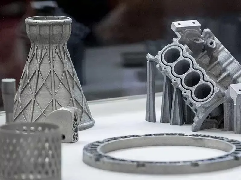
How rapid prototyping using 3D printing builds a part
Additive manufacturing slices a CAD solid into layers, then deposits or cures material one layer at a time. Layer height sets the vertical resolution: 0.1 mm gives a smooth wall, 0.25 mm prints roughly twice as fast with visible stair-stepping on curved faces.
The build direction matters more than most people expect. A hole printed along the Z axis comes out slightly oval; the same hole printed in the XY plane holds roundness much better. Rotate the part in the slicer before you complain about the diameter.
Anisotropy is the second thing to internalize. FDM parts are strong along the extrusion path and weak across layer bonds, often losing 30-50% of tensile strength in the Z direction. If the prototype will be loaded, orient it so the load runs along the layers, not across them.
Every process also needs support material somewhere. Overhangs steeper than about 45° from vertical, internal channels, and deep pockets all need support. On a prototype that means witness marks on the surface and extra time in post-processing to cut, dissolve, or blast it away.
- 1Layer height0.05 mm fine, 0.1 mm standard, 0.25 mm draft
- 2Build orientationDecide it before quoting, not after
- 3Support removalBudget time for every overhang past 45°
- 4ShrinkageSLS and MJF run 2-3% linear, plan the offset
Which 3D printing process fits which prototype
SLA and DLS cure resin with a laser or projector. They give the smoothest as-printed surface, down to roughly Ra 1.6 μm, and hold fine features like 0.3 mm walls. Good for form-and-fit models, clear parts, and anything that will be sanded and painted. Bad for parts that sit in sunlight or take a load.
SLS and MJF sinter nylon powder without support structures, because the surrounding powder holds the part up. That means nested geometry, living hinges, and internal channels come out clean. Surface is grainy, like 220-grit paper. Both are the workhorses for functional brackets and housings.
FDM extrudes a thermoplastic filament. It is the cheapest per cubic centimeter and the easiest to run in-house, but it is also the weakest and the least accurate. Use it for jigs, rough mockups, and enclosures where nobody measures the wall.
Metal printing splits into DMLS and binder jetting. DMLS gives near-wrought density in Ti-6Al-4V, 316L, and Inconel, with real mechanical properties, at a cost that usually only makes sense for lattice structures or conformal cooling. Binder jetting is cheaper per part but needs a sintering step and shrinks about 20%, so plan the compensation.
Material jetting and PolyJet print multiple materials in one build, including soft durometers and transparent resins. Excellent for over-molded grips, gaskets, and color models. The trade-off is cost and UV stability, so it is rarely the choice for a part that will be tested for months.
Tolerance and surface limits you should plan around
No polymer 3D printing process holds ±0.005 mm. Typical best-case on a well-tuned machine is ±0.1 mm on the first inch, then ±0.2% of the remaining dimension. A 100 mm nylon part can drift 0.3 mm at the far end without anything being wrong.
That number is fine for a housing that mates with a gasket. It is not fine for a bearing bore, a press-fit pin, or a thread that must take torque. When the drawing says ±0.05 mm, additive is the wrong tool, full stop.
Z-axis accuracy is worse than XY on every process. If a critical feature runs vertically, rotate the part or accept the tolerance. Similarly, small holes print undersize by 0.1-0.2 mm on average, so drill or ream them after printing if the fit matters.
Surface finish is the other hidden cost. As-printed SLS nylon sits around Ra 6-10 μm. Bead blasting brings it to roughly Ra 3-5 μm. Vapor smoothing or resin coating can push a part closer to Ra 1.6 μm, but it adds a day and changes the dimensions slightly.
When to move from 3D printing to CNC machining
The switch usually happens for one of three reasons: the material needs to be metal, the tolerance needs to be tight, or the part needs to survive a real test cycle. None of those are failures of additive. They are just different jobs.
CNC machining holds ±0.005 mm and Ra 0.2-0.8 μm on a finishing pass. The same aluminum bracket that came off an SLS printer with a grainy surface and ±0.15 mm walls comes off a 5-axis mill with a mirror finish and bores that gauge correctly. For functional testing, that difference decides whether the data means anything.
The trade-off is setup. A printed part has no fixturing, no tooling, and no minimum order. A machined part needs a program, a vise or soft jaws, and a first-article check. That is why the usual path is print for geometry, machine for function.
At GreatLight we run both. A typical program starts with 3D-printed form models for ergonomic and packaging checks, then moves to CNC-machined functional prototypes in 6061-T6, 316L, or PEEK for load and thermal testing before tooling. Quotation and free DFM analysis come back within 12 hours, and production can start within 24 hours.
- 1Print it ifGeometry, ergonomics, or packaging fit is the question
- 2Machine it ifMaterial properties, tolerance, or thermal behavior is the question
- 3Do both ifYou have a design review and a test cycle in the same month
3D printing vs CNC machining for prototypes
Use this table to pick the process before you send files out.
| Factor | 3D printing | CNC machining |
|---|---|---|
| Typical tolerance | ±0.1 mm to ±0.3 mm | ±0.005 mm |
| Surface finish | Ra 3-10 μm as-printed | Ra 0.2-1.6 μm |
| Material range | Resins, nylon, limited metals | Aluminum, steel, titanium, plastics |
| Setup cost | None | Program plus fixturing |
| Best for | Complex geometry, internal channels | Tight fits, load-bearing parts |
| Lead time | 1-3 days typical | 3-5 days after DFM |
| Minimum order | One part | One part |
| Repeatability | Build-to-build drift | Held by the program |
The short verdict
If the question is shape, print it. If the question is fit, load, or finish, machine it. Printing a part and hoping it behaves like metal is the most expensive mistake in prototyping.
Questions engineers ask before sending files
Can a 3D-printed prototype be used for functional testing?
Yes, with the right process and material. SLS and MJF nylon parts handle snap fits, clips, and moderate loads well. DMLS metal parts behave close to wrought material in Ti-6Al-4V, 316L, and Inconel.
No if the test is about fatigue, thermal cycling, or a tight interference fit. Those need machined metal, because layer bonds and residual porosity change the result.
How much does the build orientation actually change the part?
More than most people expect. Roundness, hole diameter, and tensile strength all shift with orientation. A vertical hole can come out 0.2 mm oval.
Set the orientation in the slicer and check the critical features on the drawing before you approve the build. If a feature is orientation-sensitive, mark it on the model.
What wall thickness is safe to print?
SLA and DLS hold 0.3-0.5 mm walls reliably. SLS and MJF prefer 0.8-1.0 mm to survive powder removal and handling.
FDM needs 1.2 mm or more, or two perimeters, to avoid a flimsy wall. Anything thinner should be modeled as solid.
Do I need to compensate for shrinkage?
On SLS and MJF nylon, yes. Expect 2-3% linear shrinkage, and let the service apply the offset rather than scaling the CAD yourself.
On binder jetting metal, shrinkage is closer to 20% through sintering. That is handled by the process simulation, but it limits how tight the final tolerance can be.
When should I stop printing and go straight to CNC?
When the drawing calls for ±0.05 mm or tighter, when the material must be aluminum, steel, or titanium, or when the part will be tested for weeks.
Printing a geometry check first is still worth it. It is cheap, it catches design errors, and it keeps the machined prototype from becoming an expensive iteration.
Can the same CAD file go to both processes?
Usually yes, with edits. Add machining stock to faces that will be finished, remove features too small for the tool, and check the minimum internal radius against the cutter.
For printed versions, thicken thin walls and add drain holes for trapped powder or resin. The DFM pass we run within 12 hours catches most of this before quoting.
Send the model, get a real answer on process and cost
Upload your CAD and we will tell you whether to print it, machine it, or do both. Quotation and free DFM analysis within 12 hours. No minimum order, from one prototype to 10,000+ parts.
12-hour quote100% inspectionNDA on request
More prototyping notes from the shop floor
We publish setup notes, tooling trials and inspection data from the factory floor.











